Page 13 - Manual FA01625-EN - 02/2023 - © CAME S.p.A. - The contents of this manual may be changed at any time and without notice. - Translation of the original instructions
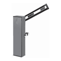
Boom installation
Insert the boom between the boom attachment and the boom anchoring plate and fasten using screws.
First install the LED strip (where applicable), ONLY THEN fix the flange and the intermediate plate.
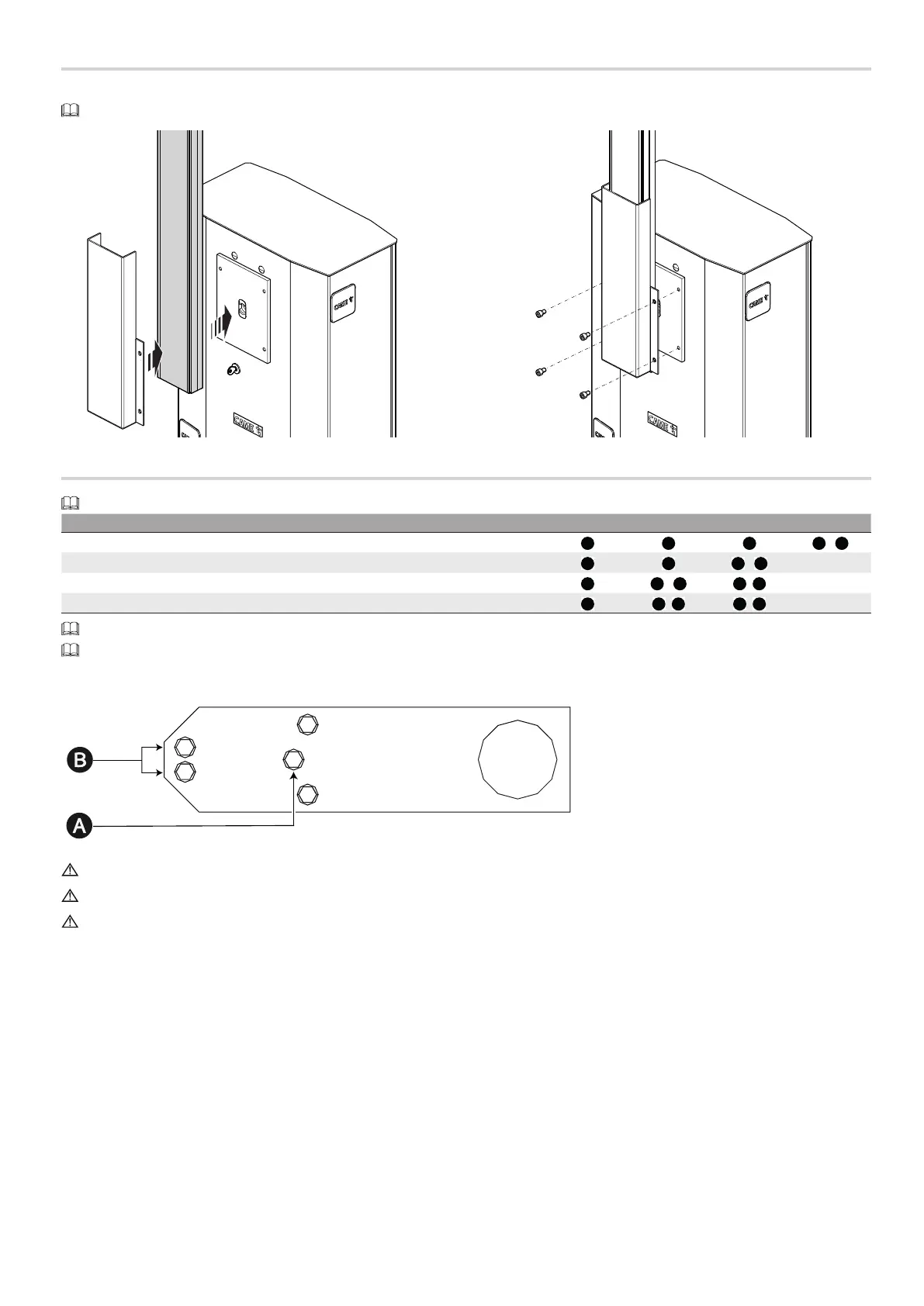
Choosing the hole for fixing the balance spring
The barrier is supplied as standard with springs (Ø 50 mm) fitted in the holes marked B.
Passage width clearance (m) 3 < 4 4 < 5 5 < 6 6 < 6,5
Boom
A A B A
B
Boom with warning lights (001G0460)
A B A
B
Boom with warning lights and skirt (001G0465)
B A
B B
B
Boom with warning lights and swing rest (001G02808)
B A
B B
B
Simple boom means the boom complete with slot cover, cap and rubber profile.
If the passage is wider than 3 m, you must use a support for the boom (fixed or mobile).
The fixed rest (001G02807) must be used for passage clearance widths exceeding 3 metres.
The swing rest 001G02808 and the skirt 001G0465 cannot be used together.
The DIR photocell support (001G02802) cannot be used with skirt 001G0465 or swing rest 001G02808.
 Loading...