Page
5 - Manual FA01869-EN - 08/2022 - © CAME S.p.A. - The contents of this manual may be changed, at any time, and without notice. - Translation of the original instructions
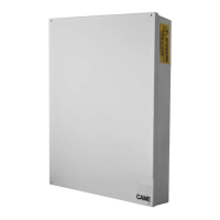
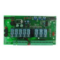
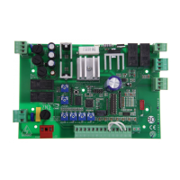
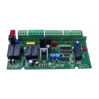
Control unit installation
CONTROL UNIT PXC2 TECHNICAL CHARACTERISTICS
DESCRIPTION
PXC2-32 PXC2-64 PXC2-212
Basic connection points in the control unit
888
External connection points
24 56 204
Total connection points
32 64 212
RS485 Bus lines
122
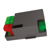
Number of I/O wire modules
Connectable on bus
16 PX4IOR
32 PX4IOR
Distributed on the 2 bus lines
64 PX4IOR
Distributed on the 2 bus lines
Control unit relay outputs (programmable)
123
Areas
4816
Scenarios
32 32 32
Key readers
4816
Keypads
4 (1 wired, 3 wireless or
wired)
8 (1 wired, 7 wireless or
wired)
16 (1 wired, 15 wireless or
wired)
Transponder keys
99 999 999
Digital key combinations 1,000,000 1,000,000 1,000,000
User codes
99 999 999
Transmitters
83232
Wireless receivers on bus
2816
Events (*)
1,000 10,000 10,000
PSTN module
Optional (PXTEL01)
3G Module
Optional (PXMC3G)
Processing and signal priorities 1) Alarm/burglary, 2) Sabotage, 3) Fault/Exclusion
Speech synthesis
Standard
Telephone numbers
81632
Power-supply units on BUS
248
LAN interface
Standard Standard Standard
Control via SMS
With PXMC3G module
Remote control with voice guidance
With PXSV and PXTEL01 or PXMC3G modules
Wi-Fi connection
Through PXWIFI module
Cloud Connection
Standard
Live video check (ONVIF cameras)
With PXONV module
ID Contact protocol on PSTN
With PXTEL01 module
ID Contact protocol on GSM
With PXMC3G module
SIA-IP protocol
With PXMC3G module or via LAN
Power supply unit (A)
235
Casing
Metal Metal Metal
Dimensions
(405x295x90) 405x295x90 490x360x90
Fittable battery (Ah)
7.2 17 17
Environmental class
222
Regulatory compliance
EN 50131-6, EN 50131-
Grade 2
EN 50131-6, EN 50131- 3
Grade 2
EN 50131-6, EN 50131- 3
Grade 3
(*) Control unit events are stored in a non-volatile FLASH memory that does not require power to guarantee data storage. A minimum
data storage life of 40 years is guaranteed.
 Loading...