7
+0500040RU - 1.2 - 07.06.2011
ENG
The versions with valve driver, with or without Ultracap module, have the same number, type and con guration of I/Os as the
Medium version.
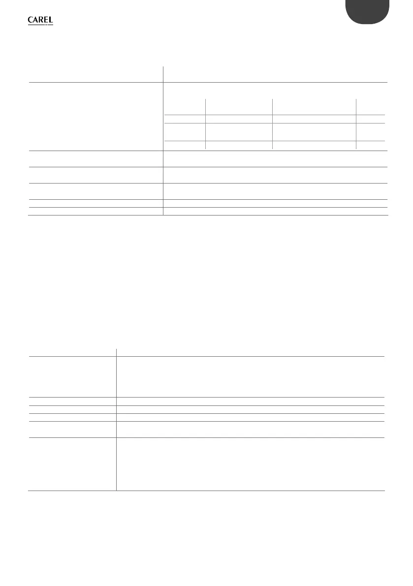
Digital inputs
type ID1 to ID18 optically-isolated (voltage contact), B4, B5, B9, B10 non optically-
isolated (free contact)
maximum number voltage inputs optically-
isolated
8: SMALL; 14: MEDIUM & EXTRALARGE ; 18: LARGE. As per combinations shown
below:
no. 24 Vac opto inputs
50/60 Hz o 24 Vdc
no. 24 Vac/Vdc or 230 Vac opto
inputs (50/60 Hz)
total
inputs
SMALL 8 none 8
MEDIUM/
EXTRALARGE
12 2 14
LARGE 14 4 18
maximum number inputs free contact not
optically-isolated
2: SMALL, MEDIUM & EXTRALARGE (B4 and B5);
4: LARGE (B4, B5, B9, B10)
Classi cation of measurement circuits (IEC EN
61010-1)
Categor
y 1 (J5, J7, J20) 24 Vac/Vdc - Category 3 (J8, J19) 230 Vac
Voltage-free digital input current
(B4, B5, B9, B10)
5 mA
Digital input current with 24 Vac voltage signal 5 mA
Digital input current with 230 Vac voltage signal 5 mA
WARNINGS: - IDH digital inputs 230 Vac 50/60 Hz (10/-15%) protected by a single 500 mAT fuse;
- the two 230/24 Vac inputs at J8 and J12 have the same common and so both will be either
24 Vac/Vdc or 230 Vac. There is double insulation between the two inputs and the rest of the controller;
- the external contact connected to the digital inputs must have a minimum current of 5 mA;
- for DC digital inputs (Vdc), either the + or the – can be connected to the common (IDC1).
Note: separate as much as possible the probe signal and digital input cables from the cables to inductive loads and power cables,
to avoid possible electromagnetic disturbance.
Fast digital input speci cations (B4 and B5 voltage-free contact)
When con gured as fast digital inputs, B4 and B5 can measure a signal with a maximum frequency of 2 KHz and a resolution of ±1
Hz. This is possible as the BIOS provides the application program two pairs of variables that count the zero crossing of the input
signal and the corresponding frequency in Hz.
Analogue inputs
analogue conversion 10-bit A/D converter embedded in CPU
type universal: (inputs B1, B2, B3, B6, B7, B8) CAREL NTC temperature sensor (-50T90 °C; R/T 10 k at 25 °C),
NTC HT 0T150 °C, voltage: 0 to 1 Vdc, 0 to 5 V ratiometric or 0 to 10 Vdc, current: 0 to 20 mA or 4
to 20 mA, selectable via software. Input resistance for 0 to 20 mA= 100
passive: (inputs B4, B5, B9, B10) CAREL NTC temp. sensor (see universal),
PT1000 (-100T200 °C; R/T 1000 at 0°C) or volt.-free digital input (5 mA), selected via software;
maximum number 5: SMALL; 8: MEDIUM & EXTRALARGE; 10: LARGE
time constant for each input 0,5 s
precision ± 0.3 % of full scale
class. of measurement circuits
(IEC EN 61010-1)
Categor
y 1
input impedance
NTC 10 kΩ
4-20 mA 100 Ω
0-1 V
100 kΩ
0-5 V 20 kΩ
0-10 V 12,7 kΩ
PT1000 10 kΩ
WARNING: the 21 Vdc available at terminal +Vdc (J2) can be used to power any active probes; the maximum current is 150 mA,
protected against short-circuits. To power the 0 to 5 Vdc ratiometric probes, use the +5VREF (Imax: 60 mA) available at terminal J24.
Only use these voltages to power the active probes connected to pCO
5
.
 Loading...


