8
+0500040RU - 1.2 - 07.06.2011
ENG
Analogue outputs
type 0 to 10 Vdc optically-isolated on Y1, Y2, Y3, Y4, Y5 and Y6 / phase control on Y3 and Y4
maximum number 4: SMALL, MEDIUM & EXTRALARGE ; 6: LARGE
power supply 24 Vac/Vdc external on VG(+), VG0(-)
resolution 8 bit
maximum load 1.5 k (7 mA)
precision ± 2 % of full scale on outputs: Y1, Y2, Y3, Y4, Y5 and Y6
WARNINGS:
• A 0 to 10 Vdc analogue output can be connected in parallel to other outputs of the same type, or alternatively to an external
source of voltage. The higher voltage will be considered. Correct operation is not guaranteed if actuators with voltage inputs
are connected. Power the VG-VG0 analogue outputs at the same voltage on G-G0: Connect G to VG and G0 to VG0. This is valid
for both alternating and direct current power supplies.
• For phase control outputs (PWM), note that synchronicity (zero crossing) is taken from G/G0 and only with 24 Vac power
supply (not Vdc.
Digital outputs
type relays
max. number 8: SMALL; 13: MEDIUM; 18: LARGE; 29: EXTRALARGE
For the connections see Figs. 3 and 4 (reference NO*, NC* and C*). Note that outputs with changeover contacts are kept separate
(i.e. without poles shared between outputs). The groups of 3 outputs have 2 “common” contacts for easier installation.
Make sure that the current running through the common terminals does not exceed the rated current of an individual terminal,
that is, 8 A. Minimum relay contact current: 50 mA.
Insulation distance The relay outputs have di erent features, depending on the model of pCO
5
. The outputs can be divided
into groups. Between groups (cells in the table) there is double insulation and consequently these may
have di erent voltages. There is also double insulation between each terminal of the digital outputs and
the rest of the controller. The relays belonging to the same group (individual cell in the table) have basic
insulation and therefore must have the same power supply (24 Vac or 230 Vac).
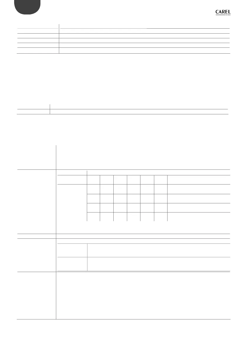
Makeup of the groups
version relays with same insulation
group
1
group
2
group
3
group
4
group
5
group
6
group
7
group
8
group
9
group
10
group
11
SMALL
Type of relay
1-3 4-6 7 8 - - - - - - -
Type A Type A Type A Type A
MEDIUM
Type of relay
1-3 4-6 7 8 9-11 12 13 - - - -
Type A Type A Type A Type A Type A Type A Type A
LARGE
Type of relay
1-3 4-6 7 8 9-11 12 13 14 15 16-18 -
Type A Type A Type A Type A Type A Type A Type A Type A Type A Type A
EXTRALARGE
Type of relay
1-3 4-6 7 8 9-11 12 13 14-16 17-20 21-24 25-29
Type A Type A Type A Type A Type A Type A Type A Type B Type B Type B Type B
NOTE: the relays in the individual cells of the table have basic insulation, while there is double insulation
between groups of cells.
Changeover contacts 1: SMALL (relay 8); 3: MEDIUM & EXTRALARGE (relays 8, 12 & 13); 5: LARGE (relays 8, 12, 13, 14 & 15)
Switchable power warning: the relay outputs have different features, depending on the model of pCO
5
type A relay relay type: SPDT, 2000 VA, 250 Vac, 8 A resistive
pCO5 approval: UL60730: 2A 250 Vac resistive, C300 pilot duty 240 Vac (30.000 cycles)
EN 60730-1: 2 A resistive, 2 A inductive, cos= 0.6, 2(2) A (100,000 cycles)
type B relay (only
EXTRALARGE
version)
relay type: SPDT, 1250 VA, 250 Vac, 5 A resistive
pCO5 approval: UL60730: 1A 250 Vac resistive, C300 pilot duty 240 Vac (30.000 cycles)
EN 60730-1: 1 A resistive, 1 A inductive, cos= 0.6, 1(1) A (100,000 cycles)
SSR outputs
(optional on the mo-
dels where featured)
1: SMALL (output 7); 2: MEDIUM & EXTRALARGE (outputs 7 & 12); 3 or 4: LARGE (outputs 7, 12 & 14 or 7,
12, 14 &15)
Operating voltage: 24 Vac/Vdc; Maximum load current = 0,5A; Maximum pulse load current = 1,2A.
If the load requires a higher current, use an external SSR.
To power external loads, use the same power supply as the pCO (connected to terminals G/G0); as
speci ed by Carel, this must always be dedicated and not in common with the power supply to other
devices on the electrical panel (such as contactors, coils, etc.).
Make sure that the load connection cables are as short as possible and away from power cables. For the
connection diagrams see the pCOSistema manual
+0300009IT.
 Loading...


