37
7.1 Scope
Carlyle has conducted an extensive qualification program
for our R-134a compressors and has approved most
compressors for VFD applications. A summary of the
qualified models is presented in Table 18.
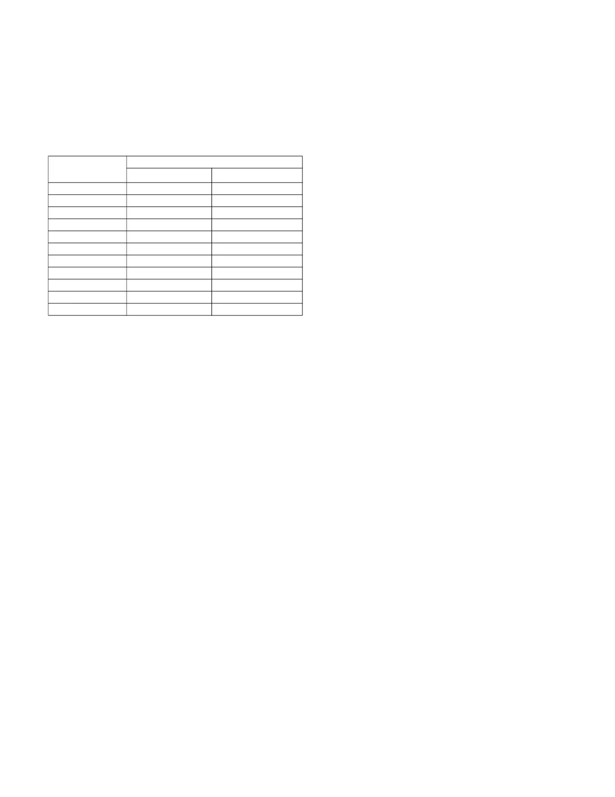
Table 18 —Variable Speed Model Summary
NOTES:
1. See Application Engineering as approval is limited to certain applica-
tions.
2. See Application Engineering as compressor has been approved but
limited
performance data is available.
3. Standard model cannot be used for VFD applications. The “VS”
model must be ordered, which is identified by an “X” in the 5th digit of
the model number.
4. Variable speed operation is approved for all low/medium temperature
R-404A, R-407A, R-407C, R407F, R-448A, R-449A, and R-507A.
It may be possible to have the drive provide the compres-
sor motor protection, replacing the compressor over-
loads. Carlyle Application Engineering should be con-
tacted to verify that the overcurrent protection meets
Car
lyle's requirements for UL-rated motor overload pro-
tection and to verify the required overload settings.
It is important to work with the drive manufacturer to
select a drive appropriate for the application. Refrigera-
tion screw compressors provide a constant torque load-
ing to the drive and also have unique starting torque
requirements. The drive should not be sized on the nomi-
nal HP rating of t
he compressor, but based on the nomi-
nal electrical data, including RLA and LRA (available in
Section 8.3), along with the operating power and amper-
age at the max load design condition. It is important that
the appropriate criteria are taken into consideration when
selecting the type and size of the drive.
It is also important to review items associated with the
wiring of the compressor and associ
ated control system
wiring, as special precautions may be required to avoid
interference between the drive and other control wiring.
There may also be restrictions on the length and routing
of the wires from the drive to the compressor. These
items should be reviewed with the drive manufacturer to
ensure all application guidelines are followed when
installing the drive.
7.2 Capacity Control
The compressors have been approved with an allowable
speed range from 30 to 60 Hz. The capacity at 30 Hz will
be approximately 50% of the full load capacity and will
vary linearly in direct proportion to the speed.
It is possible to operate the compressors with a combina-
tion of slide valve and VFD control. The compressor can
be operated at minimum speed of 30 Hz and the slide
valve used for further unload
ing as long as appropriate
discharge and motor temperature limits are observed.
The compressor slide valve should remain in the fully
loaded position while the VFD is controlling compressor
capacity between 30 to 60 Hz. The slide valve may be
used to reduce compressor capacity below 50% (30hz) if
required.
Discharge Temperature
1. Compressor must be forced to 100% load if discharge
temperature 200°F (93.3°C).
2.
Unloading control must limit further unloading if dis-
charge temperature 190°F (87.8°C)
Motor Temperature
1. Compressor must be forced to 100% load if motor tem-
perature 265°F (129.4°C).
2. Unloading control must limit further unloading if motor
temperature 260°F (126.7°C)
NOTE: Different temperature limits may be required
depending on the accuracy and response time of the
sensors and control system that is used as well as the
overall stab
ility of the system and desired safety factor.
7.3 Power Supply
The variable speed drive should fix the output voltage
based on a constant Volts-per-Hz curve running through
the nominal voltage (380V/60Hz, 460V/60Hz) regardless
of the nominal voltage supplied to the drive. The drive
should maintain a constant V-Hz over the range of opera-
tion and should limit the speed of the drive if the appropri-
a
te voltage cannot be maintained. Over voltage should
be limited to +10% and under voltage limited to –15%.
Under voltage should limit the speed (Hz) until the con-
stant V-Hz curve is reached. Over voltage should limit
operation at the maximum speed, 60 Hz. The VFD
should also limit the amperage of the compressor to
90% of the MCC (maximum continuous current) value
(lower amperage limits may be applied depending on the
application). It may be neces
sary to limit the speed of the
MODEL
NUMBER
APPROVED FOR VARIABLE SPEED
AIR-COOLED
WATER-COOLED
3
06TS-137 Note 1 and 2 N/A
06TS-155 YES N/A
06TS-186 YES N/A
06TT-266 YES Note 1
06TT-301 YES Note 1
06TT-356 YES Note 1
06TU-483 YES YES, Note 3
06TU-554 YES YES, Note 3
06TV-680 YES YES, Note 3
06TV-753 Note 2 YES, Note 3
06TV-819 YES Note 2 and 3
7.0 Variable Frequency Drive Guidelines
 Loading...


