5
Fan start-up module
LED - Light Emitting Diode
Loader - Compressor capacity step
LOFF - Operating type: Local off
rEM - Operating type: by remote control contacts
SCT - Saturated disCharge Temperature
SIO - Standard Input/Output - internal communication bus
linking the basic board to the slave boards
SST - Saturated Suction Temperature
TXV - Thermal eXpansion Valve
3 - HARDWARE DESCRIPTION
3.1 - General
The control system consists of at least a basic board and a user
interface with, depending on the application, one or more slave
boards such as compressor boards, 4xDO boards or 4xAI-
2xAO boards. If used, slave boards are connected to the basic
board via an internal communication bus (SIO).
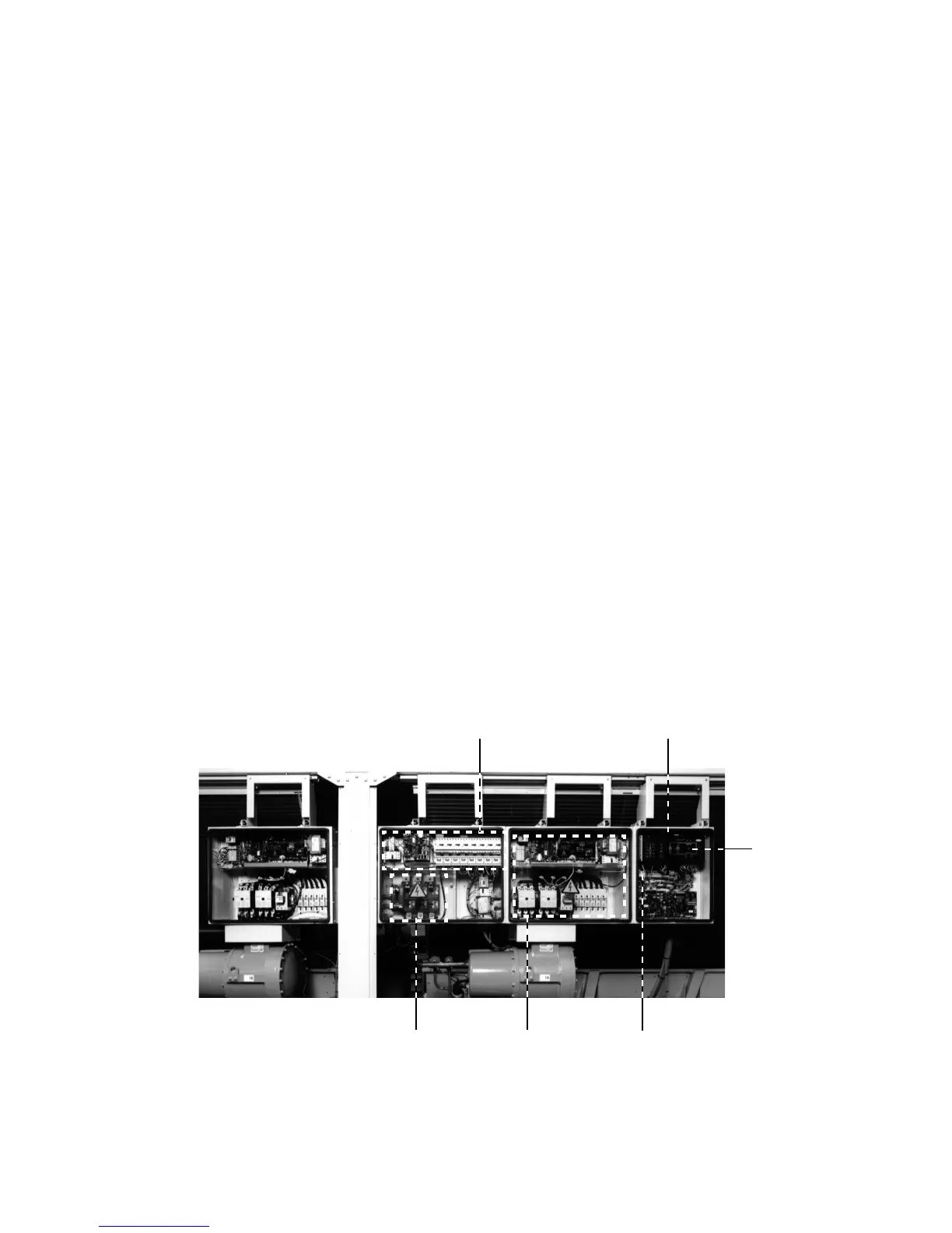
The various control components are arranged in modules
within the control cabinet:
• Control module: This comprises the basic board, the
user interface, the EXV control boards (if available) and
option boards, as well as the customer’s terminal block.
• Start-up module: This consists of the start-up boards,
compressor protection boards, as well as the compressor
circuit breakers and contactors.
• Fan module (air-cooled unit): Consists of one or two
4xDO boards together with the fan circuit breakers and
contactors.
3.2 - Electronic boards
3.2.1 - The basic board
This board can be used alone or in conjunction with slave boards.
It holds the program that controls the machine. It continuously
manages the information coming in from the various pressure
and temperature sensors, and communicates with the slave
boards via the SIO bus. It can also communicate with elements
of the Carrier Comfort Network via the CCN bus.
When “conF” shows on the user interface, this means that the
basic board must be configured. This can only be done by
Carrier Service.
Power interrupt detection: The ACF contacts on J6 detect any
interruption or dropout in the power supply. If the contact
opens, the unit is immediately shut down and the basic board is
re-initialised. This contact must therefore be normally closed
when the power to the controller is switched on. After a power
dropout, the unit restarts automatically without the need for an
external command.
3.2.2 - Slave boards
• Compressor board CPM: This board is used to control a
compressor. Up to four compressor boards can be
connected to the basic board.
• 4xDO board: This board can be used to control one EXV
(with the aid of an additional interface card), various fan
stages, loaders, oil pumps or additional motor cooling
valves.
• 4xAI-2xAO board: This board can be used to read
sensors (oil pressure, economizer pressure, condensing
temperature or reclaim temperature), or to control variable
speed fans (air-cooled units) or the condenser valve (water-
cooled units).
Control
module
Power supply
disconnect switch
Customer control
terminal block
CCN network connector
Control box
Compressor
start-up module
 Loading...