6
1 2 3 4 5 6 7 8
OPEN
Slave board addresses
BOARD DIP SWITCH (0 = open)
12345678
Board 4xDO #1 EXV circuit A 0 1 0 00010
Board 4xDO #2 EXV circuit B 0 1 1 00010
Board 4xDO #3 (fan module) #1 0 0 1 11010
Board 4xDO #4 (fan module) #2 0 0 0 00110
Board 4xDO #5 outputs compressor A1 0 0 1 00110
Board 4xDO #6 outputs compressor A2 0 0 0 10110
Board 4xDO #7 outputs compressor B1 0 0 1 10110
Board 4xDO #8 outputs compressor B2 0 0 0 01110
Board 4 x DO #9 heat reclaim module 0 0 1 01110
Board 4xAI-2xAO #1 0 1 0 10010
Board 4xAI-2xAO #2 0 0 0 01010
Board 4xAI-2xAO #3 0 1 1 01010
Blue address switch, CPM board (marked ADDRESS)
Basic
board
CPM
Compressor
board
4xDO
board
3.2.3 - The user interface
The user interface is in two parts:
• The main interface: This gives access to all of the
control parameters for the unit. It consists of a 2-digit
primary display block and a secondary 4-digit display
block with 10 LEDs and 5 buttons.
• The summary interface: This gives quick access to just
the main control parameters for the unit. It comprises 12
buttons and 16 LEDs, and includes a schematic diagram
of the unit.
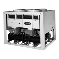
3.2.4 - Connections between boards
The basic board and slave boards communicate with each other
over an internal three-wire RS485 communication bus (SIO
bus). These three wires link all the boards in parallel.
Terminals 1, 2 and 3 on connector J4 of the basic board are
linked to terminals 1, 2 and 3 of connector J3 (except for CPM
boards where terminals 2 and 3 are reversed). Incorrect
connection will render the system inoperative.
Fig. 1 - Internal bus wiring (between boards)
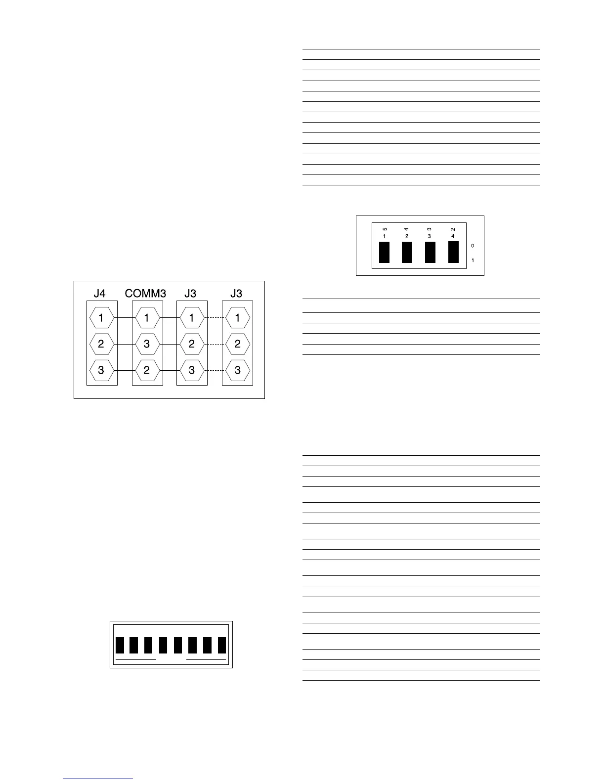
3.2.5 - Slave board addresses
Every slave board (compressor board, 4xDO or 4xAI-2xAO
board) has an address which must be set up using the red SIO
address switch (marked SIO ADDRESS) at the top righthand
corner of each board. This switch consists of 8 DIP switches
(except for the CPM boards, equipped with four blue DIP
switches). The switch is disabled when it is in the OPEN
position - (for CPM boards refer to the text engraved on the
printed circuit board).
NOTE: Any incorrect address will prevent the unit from
starting. Turn off the power before amending the address of
any auxiliary board.
Fig. 2 - Address switch - marked “SIO ADDRESS”
4AI-2AO
board
BOARD DIP SWITCH (0 = open)
5432
CPM #1 (compressor A 1) 1 0 0 1
CPM #2 (compressor A 2) 1 1 0 1
CPM #3 (compressor B 1) 1 0 1 1
CPM #4 (compressor B 2) 1 1 1 1
3.2.6 - Power supply to the boards
The basic board, the summary interface and the accessory
CCN/JBUS board are supplied from a 24 V a.c. floating
supply. The other boards are supplied by sources that are
referred to earth.
BOARDS CONNECTOR/ SUPPLY
TERMINAL 24 V a.c./WIRES
Basic board J5/ O11-O12 011-012
Summary interface J3 011-012
CCN/JBUS accessory 24 V a.c. 011-012
Compressor module A1
4xDO for A1 J1/011-012 11-1 - (12-1*)
CPM A1 PL-2/5 - 1 11-1 - (12-1*)
Compressor module A2
4xDO for A2 J1/011-012 11-2 - (12-2*)
CPM A2 PL-2/5 - 1 11-2 - (12-2*)
Compressor module B1
4xDO for B1 J1/011-012 11-3 - (12-3*)
CPM B1 PL-2/5 - 1 11-3 - (12-3*)
Compressor module B2
4xDO for B2 J1/011-012 11-4 - (12-4*)
CPM B2 PL-2/5 - 1 11-4 - (12-4*)
EXV Board J1/011-012 11 - 12
Board 4AI - 2xAO J1/011-012 11 - 12
Board 4xDO fan module #1 J1/011-012 11-11 - (12-11*)
Board 4xDO fan module #2 J1/011-012 12-11 - (12-31*)
* referred to earth
 Loading...