30 Specifications subject to change without notice. SG-38MHRC-01
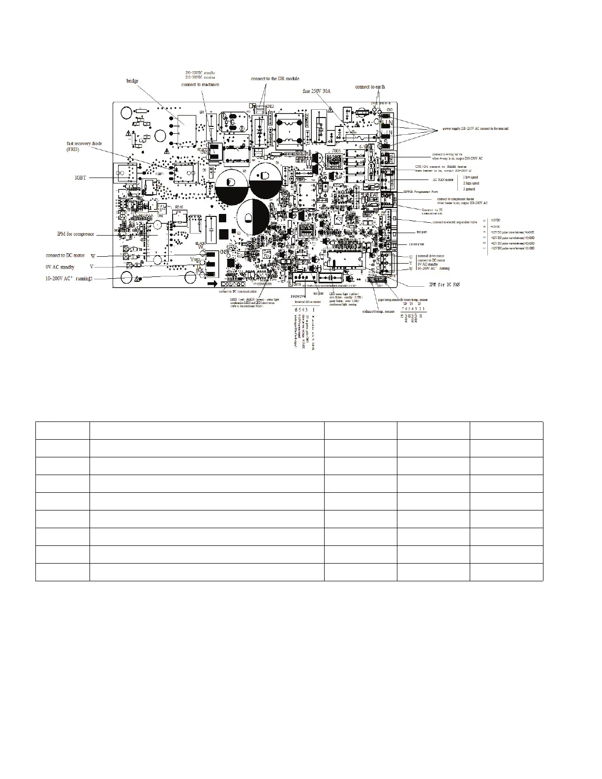
PCB DIAGRAMS (CONT)
Fig. 35 — Sizes 18-24K (208/230V)
NOTE: After power on, LED3(Green color) and LED2(Red color) will flash if the unit has some problems.
Table 14 — LED Codes
O (light) X (off) (flash)
NO. PROBLEMS LED3 (GREEN) LED2 (RED) IU DISPLAY
1 standby for normal O X
2 Operation normally X O
3 IPM malfunction or IGBT over-strong current protection
X P0
4 Over voltage or too low voltage protection O O P1
5 EEPROM parameter error O
E5
6 Inverter compressor drive error X
P4
7 Inverter compressor drive error
O P4
8 Inverter compressor drive error
P4
 Loading...