12
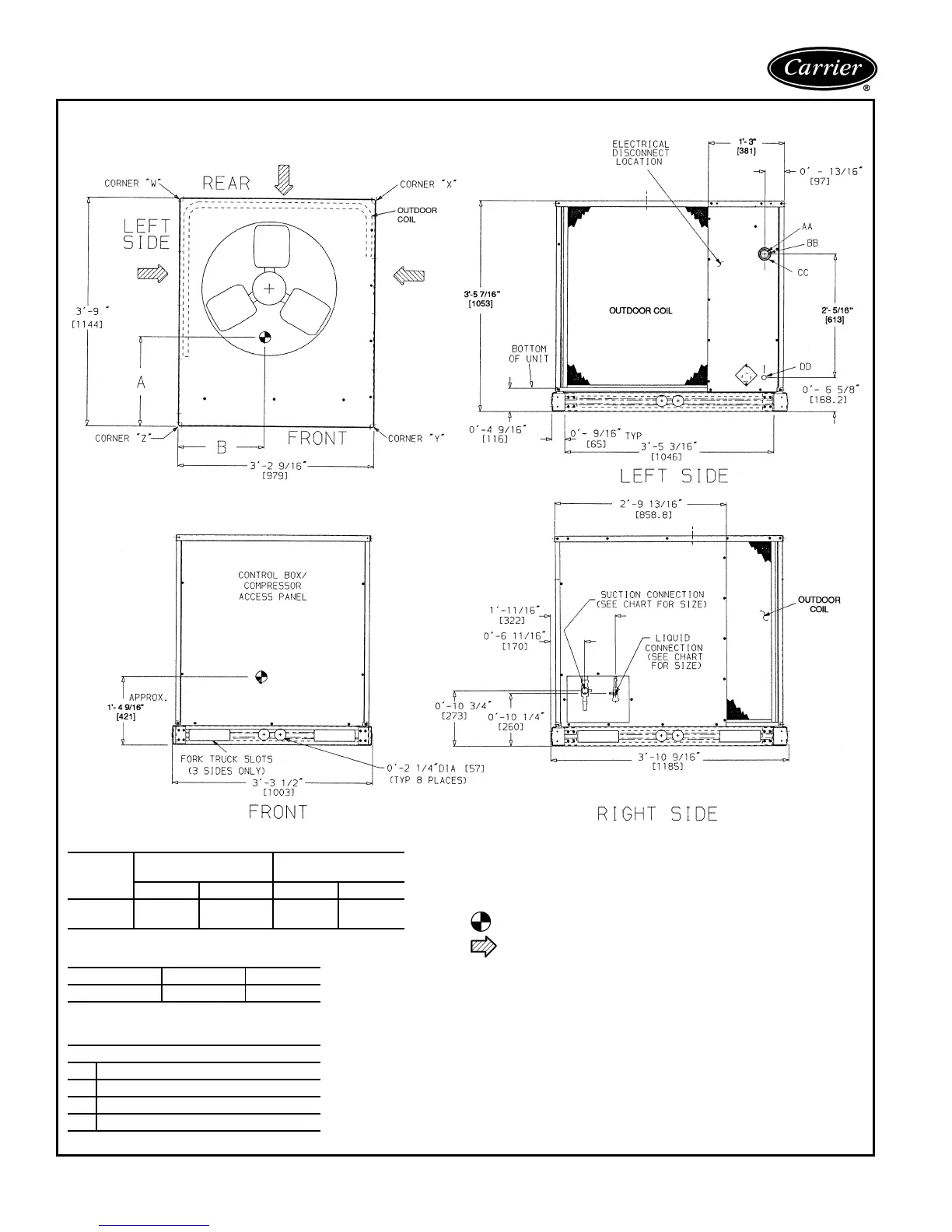
Dimensions — outdoor units
38AQS008
DIMENSION CHART
SERVICE VALVE CONNECTIONS
ELECTRICAL CONNECTIONS
UNIT
38AQS
UNIT WITH
ALUMINUM-FIN COIL
UNIT WITH
COPPER-FIN COIL
Dim. A Dim. B Dim. A Dim. B
008
1′-8″
[508.0]
1′-5″
[431.8]
1′-9
1
/
2
″
[546.0]
1′-4
3
/
4
″
[425]
UNIT 38AQS SUCTION LIQUID
008
1
1
/
8
″ [28.6]
1
/
2
″ [12.7]
CONNECTION SIZES
AA
1
3
/
8
″ Dia. [35] Field Power Supply Hole
BB
2″ Dia. [51] Power Supply Knockout
CC
2
1/
2
″ Dia. [64] Power Supply Knockout
DD
7
/
8
″ Dia. [22] Field Control Wiring Hole
NOTES:
1. Dimensions in [ ] are in millimeters.
2. Center of gravity. See Chart for dimensions.
3. Direction of airflow.
4. Minimum clearance (local codes or jurisdiction may prevail).
a. Bottom to combustible surfaces: 0 in.
b. Outdoor coil, for proper airflow: 36 in. one side, 12 in. the other. The
side getting the greater clearance is optional.
c. Overhead, 60 in. to assure proper condenser fan operation.
d. Between units: Control box side, 42 in. per NEC.
e. Between unit and ungrounded surfaces: Control box side, 36 in. per
NEC.
f. Between unit and block or concrete walls and other grounded sur-
faces, control box side, 42 in. per NEC.
5. With the exception of the clearance for the outdoor coil as stated in
note 4b, a removable fence or barricade requires no clearance.
6. Units may be installed on combustible floors made from wood or class
A, B, or C roof covering material.
 Loading...