10
HOW TO CONNECT
IMPORTANT: Please r ead following electrical
safety data carefully.
!
WARNING
ELECTRICAL SHOCK AND/OR UNIT OPERATION
AND DAMAGE HAZARD
Failure to follow this warning could result in personal injury
or death and/or unit operation and damage.
S Follow the National Electrical Code (NEC) or local
codes and ordinances.
S For personal safety, this unit MUST BE properly
grounded.
S Protective devices (fuses or circuit breakers)
acceptable for unit installations are specified on the
nameplate of each unit.
S Do not use an extension cord with this unit.
S Aluminum building wiring may present special
problems -- consult a qualified electrician.
S When unit is in STOP position, there is still
voltage to electrical controls.
S Disconnect power to unit before servicing by:
1. Removing power cord (if it has one) from wall
receptacle.
2. Removing branch circuit fuses or turning circuit
breakers off at panel.
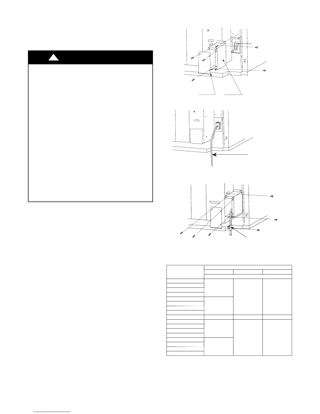
1. Remove front panel. See Fig. 11.
2. Remove junction box.
S Remove junction box cover by removing
three screws from front. Remove junction
box by taking out top, rear and side screws.
See Fig. 14.
3. Connect accessory power supply cord or hard
wire connector to unit connector. See Fig. 15.
S Units must be installed using the appropriate
power supply kit. See Table 4 -- POWER
CONNECTION CHART. These connections
must be followed.
4. Reinstall junction box and cover.
S Use wire clamp to attach power cord to
basepan. Secure with screws (included) See
Fig. 16.
S R elace junction box and cover with screws
removed from Step 2. Tighten securely.
5. Replace front panel. See Fig. 13.
6. Connect power to unit.
Unit connecto
Junction box cover
Junction box
A07058
Fig. 14 – Junction Box Location
Accessory
Power Supply Cord
or Hard Wire
A07059
Fig. 15 – Power Connection
Wire clamp
A07060
Fig. 16 – Wire Clamp
Table 4—POWER CONNECTION CHART
UNIT MODEL
CODE OF POWER SUPPLY KIT
30A 20A 15A
230/208 VOLT
5 2 M E --- U 0 7 --- --- --- 3
N/A*
P W R C O R D ---
230V---20A
P W R C O R D ---
230V---15A
5 2 M Q --- U 0 7 --- --- --- 3
5 2 M E --- U 0 9 --- --- --- 3
5 2 M Q --- U 0 9 --- --- --- 3
5 2 M E --- U 1 2 --- --- --- 3
P W R C O R D ---
230V---30A
5 2 M Q --- U 1 2 --- --- --- 3
5 2 M E --- U 1 5 --- --- --- 3
5 2 M Q --- U 1 5 --- --- --- 3
265 VOL T 265 VOL T 265 VOLT
5 2 M E --- U 0 7 --- --- --- 4
N/A*
P W R C O R D ---
265V---20A
P W R C O R D ---
265V---15A
5 2 M Q --- U 0 7 --- --- --- 4
5 2 M E --- U 0 9 --- --- --- 4
5 2 M Q --- U 0 9 --- --- --- 4
5 2 M E --- U 1 2 --- --- --- 4
P W R C O R D ---
265V---30A
5 2 M Q --- U 1 2 --- --- --- 4
5 2 M E --- U 1 5 --- --- --- 4
5 2 M Q --- U 1 5 --- --- --- 4
* Using 30A on these units could result in damage to your unit.
 Loading...