15
TERMINAL CONNECTIONS
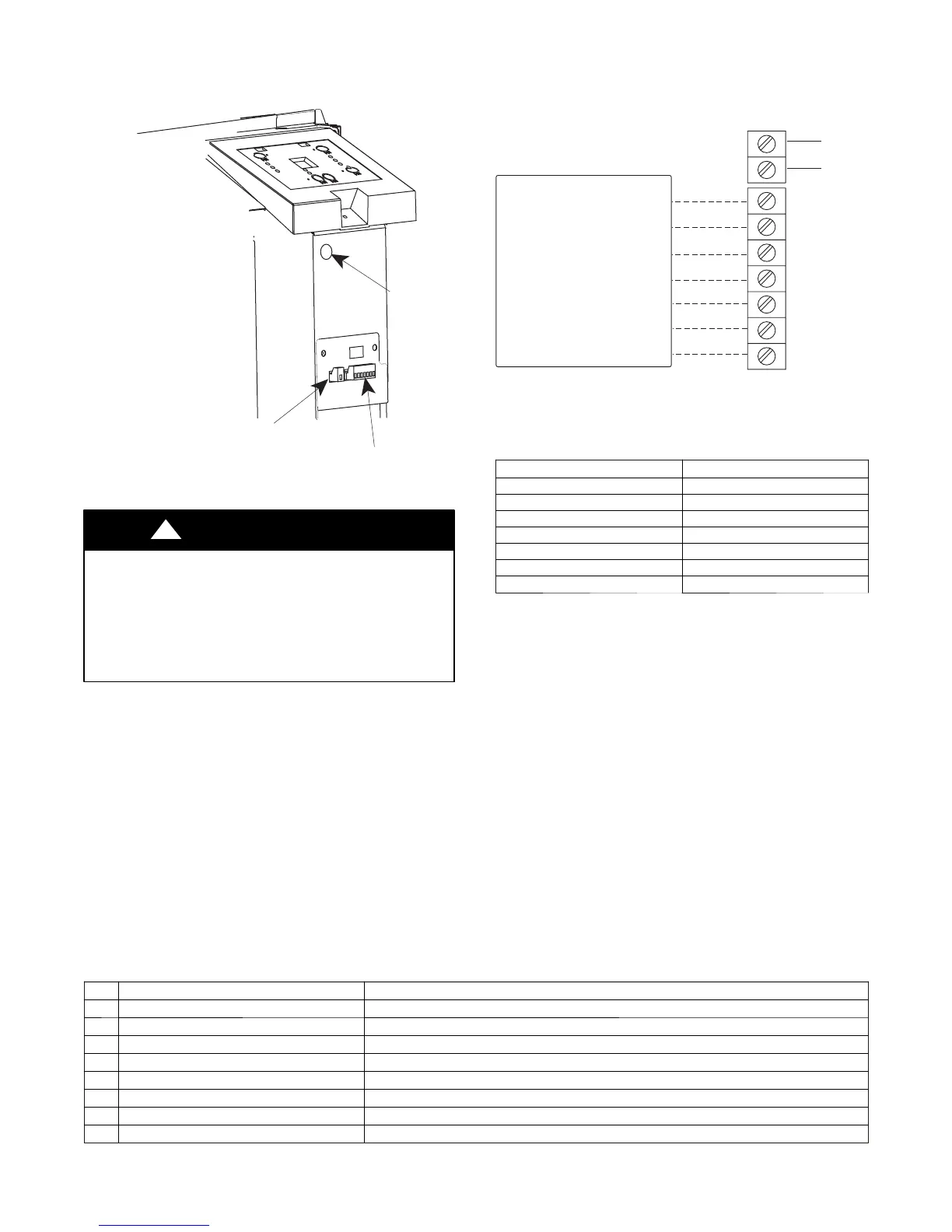
The wall t herm o s t at term i n al bl o ck is l ocat ed beh i nd t he front p anel an d is easi l y access i bl e o n fron t of contro l
panel.
STATUS LED
Wall Thermostat
Terminal Connections
Energy Management
Terminal Connections
A07088
Fig. 25 – Terminal Connector and Status LED Location
UNIT DAMAGE HAZARD
Failure to follow this caution may result in equipment
damage or improper operation.
Improper wiring may damage unit electronics. Common
busing is not permitted. Damage or erratic operation may
result.
CAUTION
!
R
Y
GH
GL
C
W
O
Common
Energy
Management
(24VAC in)
TYPICAL WALL THERMOSTAT
TERMINAL BLOCK
See Note 1
See Note 2
NOTES:
1. Use terminal “O” for heat pump connection only.
2. Terminal “C” (common) is typically only required for digital
thermostats.
A07076
TERMINAL DESIGNATION
R 24 VAC
W Electric Heat
Y Compressor
O Reversing Valve
GH High Fan
GL Low Fan
C Common
NOTE: Any illegal input combinations will be captured as thermostat wiring
failures and will light the STATUS LED indicator on main board
(see I ntelligent Self ---Checking C ontrol section)
Fig. 26 – Wiring Connections
ENERGY MANAGEMENT I NPUT (FRONT DESK CONTROL)
The controller can handle a switch signal from remote energy management input, called EM signal or front desk
control. Input must be 24VAC. If s ystem receives a 24VAC signal , it wil l turn unit off; otherwis e, the unit runs in
normal control . This functi on will be dis abled under Freeze Guard prot ection. See Fig. 25 and F ig. 26 for
terminal connections.
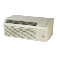
INTELLIGENT SELF--CHECKING CONTROL
Your C arrier PTAC has a computer board that continuously checks key components of t he unit to ensure t hey are
operating properly. Under normal operation, unit status indicator (STATUS, on main PCB), light is steadily ON.
If there is a major problem, the unit will shut down and display a diagnostic failure code on the unit’s display. If
it is only a minor failure and unit is correcting the fault by itself, the diagnostic code will be flashed on the status
LED that can easily be seen when the front panel is removed (see Fig. 25). F ailure STATUS codes are defined in
the table below
Table 6—STATUS LED Indicator Definitions
1 Indoor air temp sensor open/short 7 --- s e g m e n t d i s p l a y ‘F 1’, with STATUS light flash 1 time,off 2 seconds
2 Indoor coil sensor open/short 7 --- s e g m e n t d i s p l a y ‘F 2’, with STATUS light flash 2 time,off 2 seconds
3 Outdoor coil sensor open/short 7 --- s e g m e n t d i s p l a y ‘F4’, with STATUS light flash 4 time,off 2 seconds
4 Freeze Guard protection 7 --- s e g m e n t d i s p l a y ‘FP’
5 Thermostat wiring error STATUS light flash 9 times and off 3 sec, repeat
6 Indoor coil high temp protection STATUS light flash 8 times and off 3 sec, repeat
7 Defrost (heat pump type) STATUS light flash 7 times a nd off 3 sec, repeat
8 Outdoor coil high temp protection STATUS light flash 6 times and off 3 sec, repeat
9 Indoor coil freeze protection STATUS light flash 5 times and off 3 sec, repeat
NOTE: When status light is flashing, it will be ON for 0.5 seconds and OFF for another 0.5 seconds.
 Loading...