Step 2—Low-Fire Only Installation
This 58MVP furnace can be installed to operate in the low-fire
only heating mode when sized using the low-fire heating capacity.
This is accomplished by placing setup switch SW-2 in the ON
position to provide only low-fire-heat operation. See Fig. 25 and
Table 10. With this setup, high-fire operation will not occur.
When the model no. on the furnace rating plate is followed by an
asterisk (*), the furnace has an alternate low-fire only efficiency
rating as listed in the GAMA and CEC directories. This alternate
rating will be listed as the furnace model number followed by an
(-L) suffix.
The furnace can operate in the high-fire mode when certain
fault conditions occur. The following precautions should be
taken:
1. Size gas piping based on the high-fire input.
2. Check the high-fire input and adjust it per the main
literature instructions.
NEVER assume the high-fire input rate is not important for
low-fire-only installation.
Step 3—Furnace Location Relative to Cooling
Equipment
The cooling coil must be installed parallel with or on downstream
side of furnace to avoid condensation in heat exchanger. When
installed parallel with a furnace, dampers or other means used to
control flow of air must prevent chilled air from entering furnace.
If dampers are manually operated, they must be equipped with a
means to prevent operation of either unit unless damper is in
full-heat or full-cool position.
Step 4—Hazardous Locations
INSTALLATION
Step 1—Leveling Legs (If Desired)
When furnace is used in upflow position with side inlet(s), leveling
legs may be desired. (See Fig. 12.) Install field-supplied,
corrosion-resistant 5/16-in. machine bolts and nuts.
NOTE: The maximum length of bolt should not exceed 1-1/2 in.
1. Position furnace on its back. Locate and drill a 5/16-in.
diameter hole in each bottom corner of furnace. (See Fig. 12.)
Holes in bottom closure panel may be used as guide locations.
2. For each hole, install nut on bolt and then install bolt and nut
in hole. (Install flat washer if desired.)
3. Install another nut on other side of furnace base. (Install flat
washer if desired.)
4. Adjust outside nut to provide desired height, and tighten inside
nut to secure arrangement.
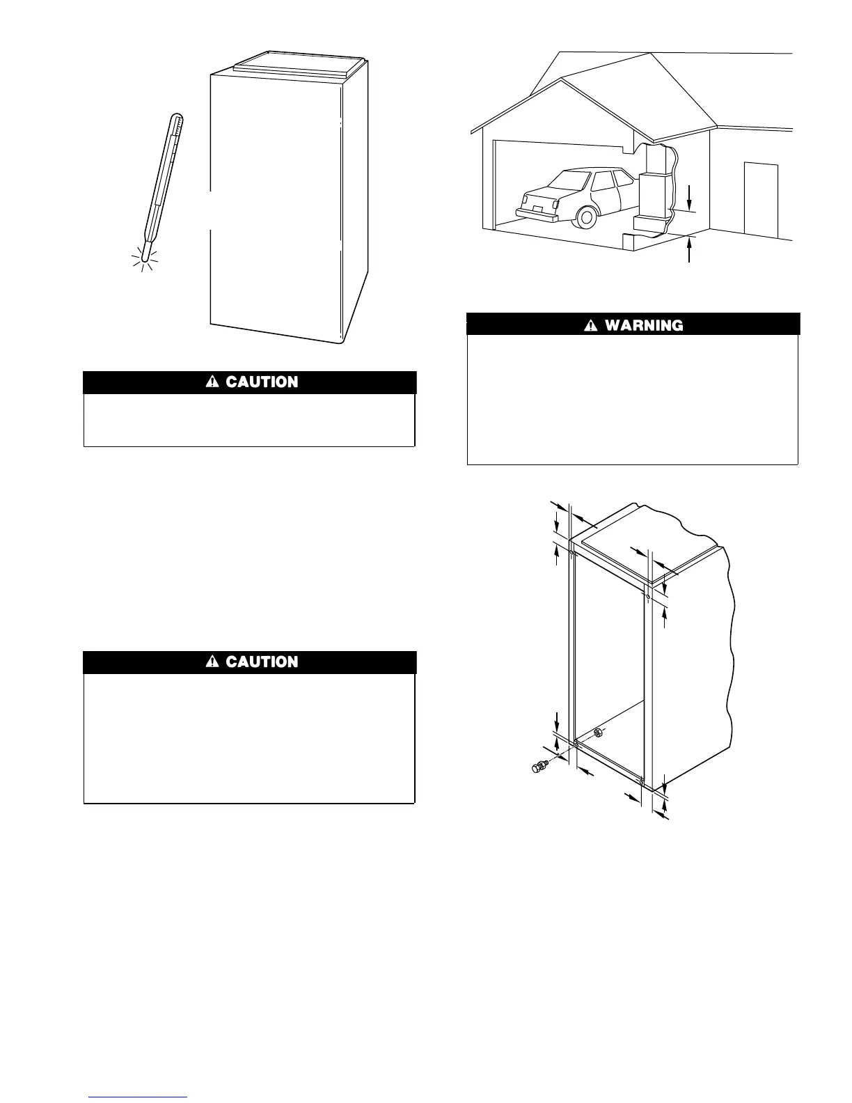
If these furnaces are installed in an unconditioned space
where ambient temperatures may be 32°F or lower, freeze
protection measures must be taken.
A93058
32°F MINIMUM INSTALLED
AMBIENT OR FREEZE
PROTECTION REQUIRED
When furnace is installed in a residential garage, it must be
installed so that burners and ignition sources are located a
minimum of 18 in. above floor. The furnace must be located
or protected to avoid physical damage by vehicles. When
furnace is installed in a public garage, airplane hangar, or
other building having a hazardous atmosphere, unit must be
installed in accordance with requirements of National Fire
Protection Association, Inc.
A93044
18-IN. MINIMUM
TO BURNERS
Fig. 12—Leveling Legs
A89014
1
3
⁄4″
1
3
⁄4″
1
3
⁄4″
1
3
⁄4″
5
⁄16″
5
⁄16″
5
⁄16″
5
⁄16″
13