When combustion-air pipe is installed above a suspended
ceiling, pipe must be insulated with 3/8-in. thick Armaflex-
type insulation. Combustion-air pipe should also be insulated
when it passes through a warm, humid space.
When vent pipe is exposed to temperatures below freezing,
such as when it passes through an unheated space or when a
chimney is used as a raceway, pipe must be insulated as
shown in Table 7 with Armaflex-type insulation.
Combustion air must not be taken from inside structure
because that air is frequently contaminated by halogens,
which include fluorides, chlorides, bromides, and iodides.
These elements are found in aerosols, detergents, bleaches,
cleaning solvents, salts, air fresheners, adhesives, paint, and
other household products. Locate combustion-air inlet as far
as possible from swimming pool and swimming pool pump
house.
Excessive exposure to contaminated combustion air will
result in safety and performance related problems.
Solvent cements are combustible. Keep away from heat,
sparks, and open flame. Use only in well ventilated areas.
Avoid breathing in vapor or allowing contact with skin or
eyes. Failure to follow this warning could result in fire,
property damage, personal injury, or death.
All combustion-air and vent pipes must be airtight and
watertight. Pipes must also terminate exactly as shown in Fig.
33, 34, 35, 36, or 37. Failure to follow this warning could
result in property damage, personal injury, or death.
NOTE: The minimum combustion-air and vent pipe length (each)
for these furnaces is 5 ft. Short pipe lengths (5-8 ft) may discharge
water droplets. These droplets may be undesirable, and a 12-in.
minimum offset pipe section is recommended, as shown in Fig. 31,
to reduce excessive droplets from exiting vent pipe outlet.
COMBUSTION-AIR AND VENT PIPE DIAMETER
Determine combustion-air and vent pipe diameter.
1. Using Table 6, individually determine the combustion-air and
vent pipe diameters. Pick the larger of these 2 pipe diameters
and use this diameter for both combustion-air and vent pipes.
2. When installing vent systems of short pipe length, use the
smallest allowable pipe diameter. Do not use pipe size greater
than required or incomplete combustion, flame disturbance, or
flame sense lockout may occur.
NOTE: Do not count elbows or pipe sections in terminations or
within furnace. See shaded areas in Fig. 34, 35, 36, 37, and 38.
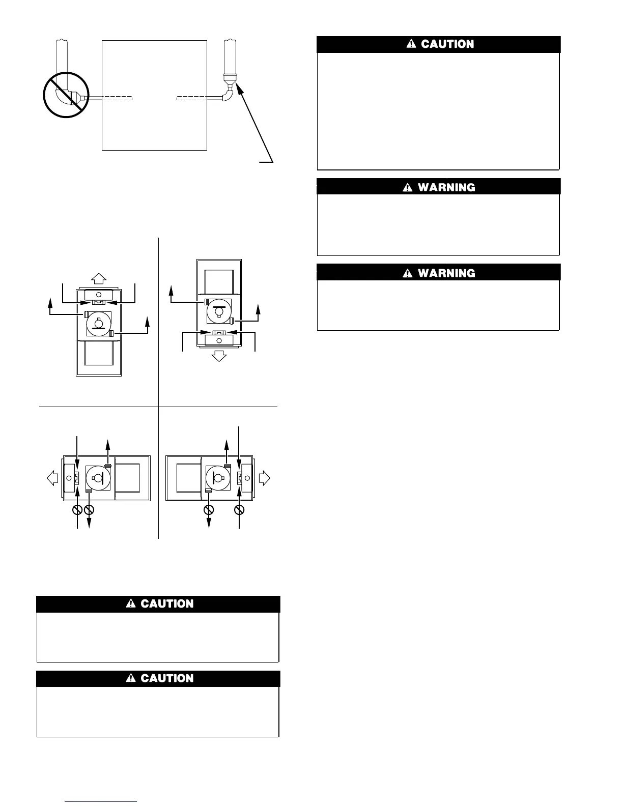
Fig. 29—Combustion-Air and Vent Pipe Diameter
Transition Location and Elbow Configuration
A93034
FURNACE
PIPE DIAMETER
TRANSITION IN
VERTICAL SECTION
NOT IN
HORIZONTAL
SECTION
Fig. 30—Combustion-Air and Vent Pipe Connec-
tions
A96187
COMBUSTION-
AIR
COMBUSTION-
AIR
AIR
FLOW
VENT
VENT
VENT
AIR
FLOW
AIR
FLOW
AIR
FLOW
UPFLOW DOWNFLOW
HORIZONTAL-LEFT DISCHARGE HORIZONTAL-RIGHT DISCHARGE
Select 1 vent pipe connection and
1 combustion-air pipe connection.
COMBUSTION-
AIR
COMBUSTION-
AIR
COMBUSTION-
AIR
COMBUSTION-
AIR
VENT
VENT
VENT
NOTE: Select 1 vent pipe connection and
1 combustion-air pipe connection.
NOTE:
24
 Loading...