26 440 01 4801 00
Specifications subject to change without notice.
Unit Size:
1202422A
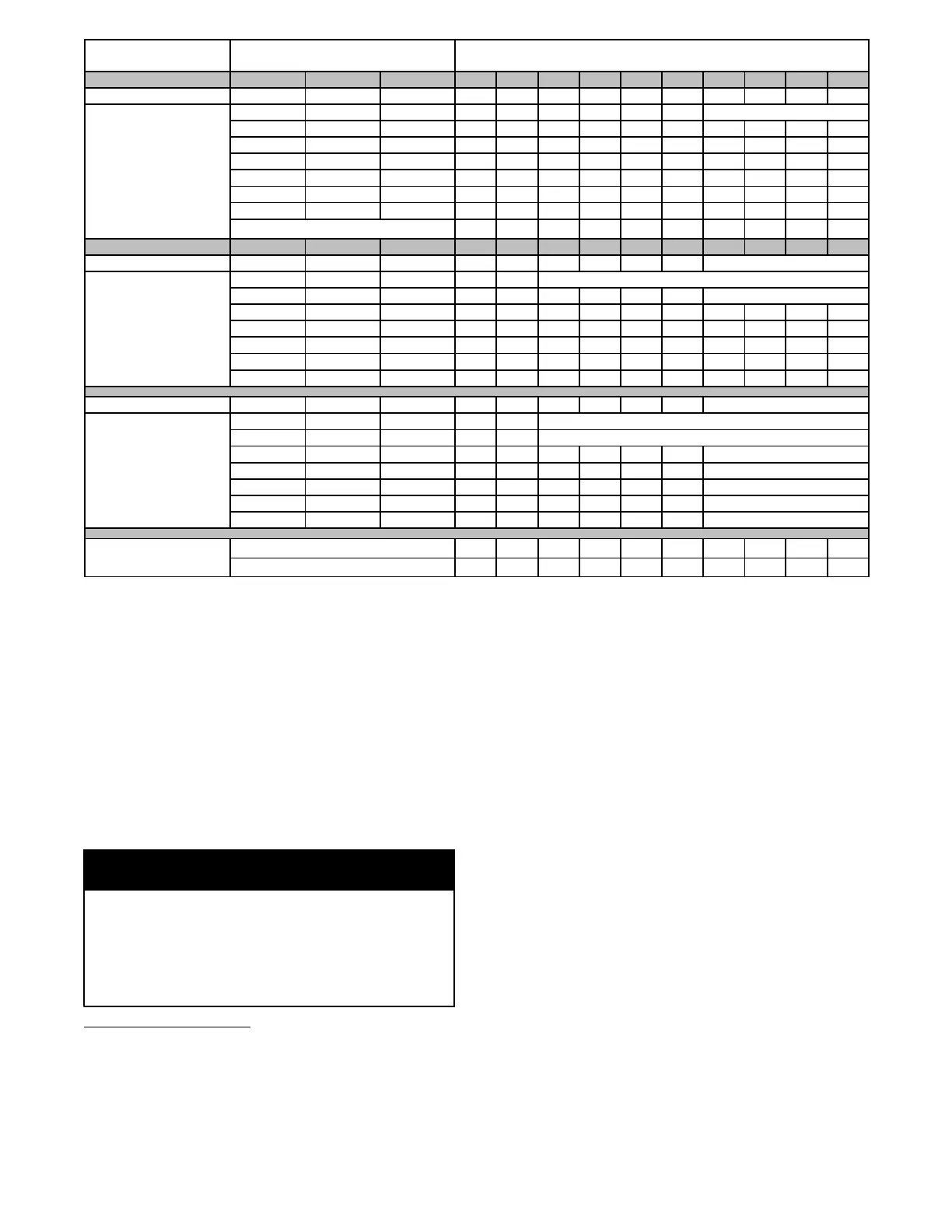
Clg/CF Switch settings External Static Pressu re (ESP)
Clg Switches: S W 2 --- 8 S W 2 --- 7 S W 2 --- 6 0.1 0.2 0.3 0.4 0.5 0.6 0.7 0.8 0.9 1.0
Clg Default: OFF OFF OFF 2060 2015 1975 1930 1885 1840 1790 1750 1705 1630
Cooling (SW2---8,7,6)
OFF OFF ON 865 775 690 595 505 425 SeeNote4
OFF ON OFF 1080 1005 935 860 785 705 625 555 490 425
OFF ON ON 1285 1220 1150 1085 1020 960 895 820 750 690
ON OFF OFF 1465 1410 1350 1285 1230 1175 1115 1060 1000 935
ON OFF ON 1685 1635 1585 1530 1475 1420 1375 1325 1270 1225
ON ON OFF 2060 2015 1975 1930 1885 1840 1790 1750 1705 1630
ON ON ON 2265 2225 2180 2145 2100 2060 2010 1895 1770 1645
Maximum Clg
irflow
2320 2310 2270 2230 2190 2135 2020 1895 1770 1645
CF Switches S W 2 --- 5 S W 2 --- 4 S W 2 --- 3 0.1 0.2 0.3 0.4 0.5 0.6 0.7 0.8 0.9 1.0
L o w --- C l g D e f a u l t : OFF OFF OFF 865 775 690 595 505 425 SeeNote4
L o w --- C o o l i n g
(SW2---5,4,3)
OFF OFF ON 585 470 SeeNote4
OFF ON OFF 865 775 690 595 505 425 SeeNote4
OFF ON ON 1080 1005 935 860 785 705 625 555 490 425
ON OFF OFF 1285 1220 1150 1085 1020 960 895 820 750 690
ON OFF ON 1465 1410 1350 1285 1230 1175 1115 1060 1000 935
ON ON OFF 1685 1635 1585 1530 1475 1420 1375 1325 1270 1225
ON ON ON 2060 2015 1975 1930 1885 1840 1790 1750 1705 1630
Cont. Fan Default: OFF OFF OFF 865 775 690 595 505 425 SeeNote4
Continuous Fan
(SW2---5,4,3)
OFF OFF ON 585 470 SeeNote4
OFF ON OFF 730 630 SeeNote4
OFF ON ON 865 775 690 595 505 425 SeeNote4
ON OFF OFF 865 775 690 595 505 425 SeeNote4
ON OFF ON 865 775 690 595 505 425 SeeNote4
ON ON OFF 865 775 690 595 505 425 SeeNote4
ON ON ON 865 775 690 595 505 425 SeeNote4
Heating (SW1)
High Heat
irflow
2165 2120 2075 2030 1985 1940 1895 1850 1770 1645
Low Heat
irflow
1675 1625 1575 1525 1475 1425 1375 1325 1275 1225
NOTE: See notes at end of table.
Tabl e 9 -- Cooling
4
and Heating Air Delivery -- CFM (Bottom Return
5
with Filter) -- NOTES
1. Nominal 350 CFM/ton cooling airflow is delivered with SW1---5 and SW2---2 set to OFF.
Set both SW1 ---5 and S W2 ---2 to ON for +7% airflow ( nominal 370CFM/ton) .
Set SW1---5 to ON and SW2---2 to OFF for +15% a irflow (nominal 400C FM/ton )
S e t S W 1 --- 5 t o O F F a n d S W 2 --- 2 t o O N f o r --- 7 % a i r f l o w ( n o m i n a l 3 2 5 C F M / t o n )
The above adjustments in airflow are subject to motor horsepower range/capacity
This applies to Cooling and Low---Cooling airflow, but does not affect continuous fan airflow.
2 . M a x c o o l i n g a i r f l o w i s a c h i e v e d w h e n s w it c h e s S W 2 --- 6 , S W 2 --- 7 , S W 2 --- 8 a n d S W1 --- 5 a r e s e t t o O N , a n d S W 2 --- 2 i s s e t t o O F F.
3. All heating CFM’s are when comfort/efficiency adjustment switch SW1 ---4 is set to OFF.
4. Ductwork must be sized for high ---heating CFM within the operational range of ESP. Operation within the blank areas of the chart is not recommended be-
cause high ---heat operation will be above 1.0 ESP.
5. All airflows on 21” (533 mm) casing size furnaces are 5% less on side---retur n only installa tions.
6. Side return s for 24.5” (622 mm) casing sizes require two sides, or a side an d bottom to all ow sufficient a irflow at the return of the fur nace.
7. Airflows over 1800 CFM requ ire bottom return, two---side r etu rn, or bottom and side return or excessive watt draw may r esult. A minimum filter size of
20x25” (508 x 635 mm) is required.
AIR DUCTS
Many states, provinces and localities are considering or have
implemented standards and/or restrictions on duct sizing
practices, ductwork leakage, and/or ductwork thermal, airflow
and electrical efficiencies. CONSUL T LOCAL CODE
OFFICIALS for ductwork design and performance
requirements in your area.
NOTICE
General Requirements
The duct system should b e designed and sized according to
accepted national standards such as those published by: Air
Conditioning Contractors Association (ACCA Manual D), Sheet
Metal and Air Conditioning Contractors National Association
(SMACNA) or American Society of Heating, Refrigerating and
Air Conditioning Engineers (ASHRAE) or consult The Air
Systems Design Guidelines reference tables available from your
local distributor. The duct system should be sized to handle the
required system design CFM at the design external static pressure.
The furnace airflow rates are provided in Table 9 --Air
Delivery--CFM (With Filter). When a furnace is installed so that
the supply ducts carry air circulated by the furnace to areas outside
the space containing the furnace, the return air shall also be
handled by duct(s) sealed to the furnace casing and terminating
outside the space containing the furnace.
Secure ductwork with proper fasteners for type of ductwork used.
Seal supply-- and return-- duct connections to furnace with code
approved tape or duct sealer.
NOTE: Flexible connections should be used between ductwork
and furnace to prevent transmission of vibration.
Ductwork passing through unconditioned space should be
insulated to enhance system performance. When air conditioning is
used, a vapor barrier is recommended.
Maintain a 1--in. (25 mm) clearance from combustible materials to
supply air ductwork for a distance of 36 --in. (914 mm) horizontally

 Loading...

