56 440 01 4801 00
Specifications subject to change without notice.
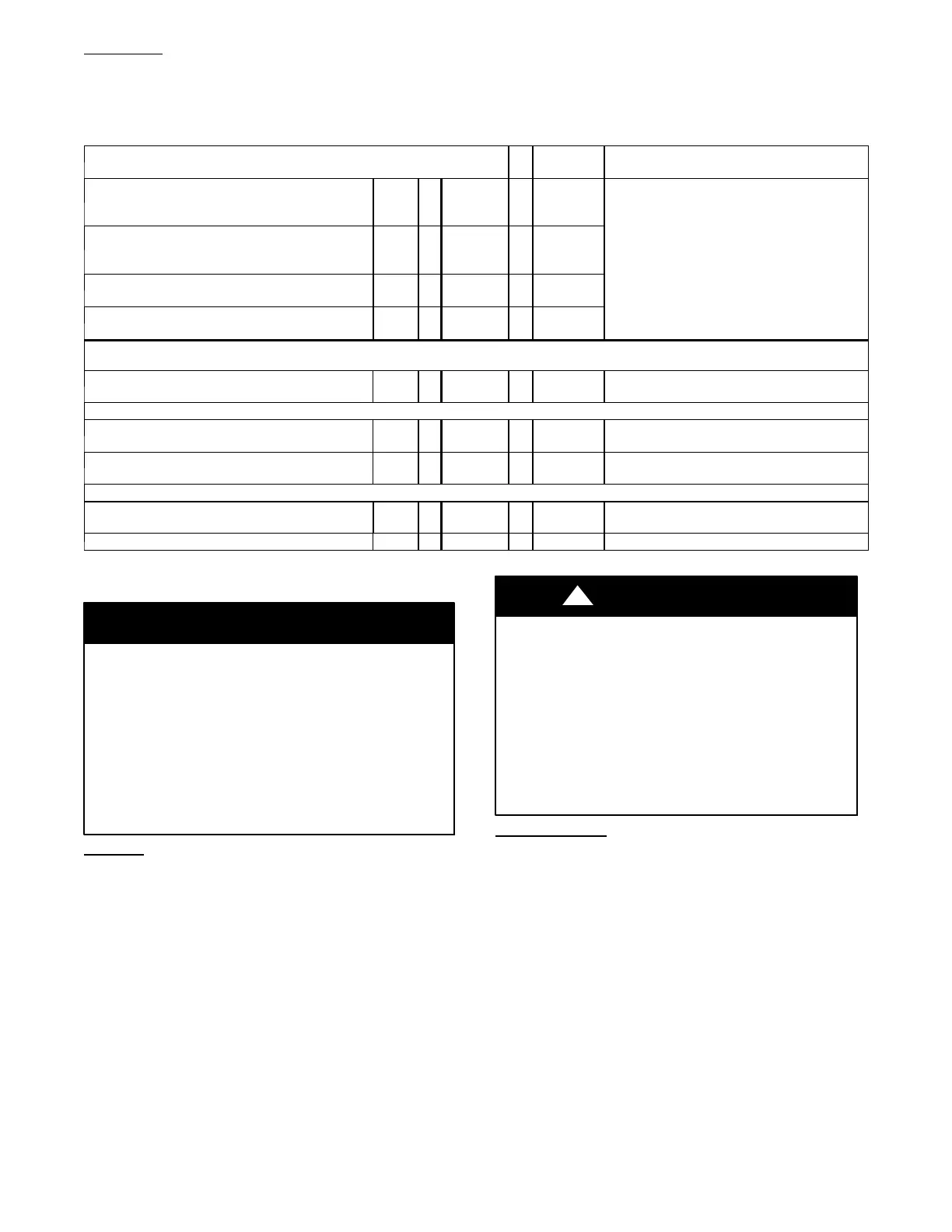
Example 2
A direct-vent 60,000 BTUH furnace installed at 2100 ft. (640M). Venting system includes FOR EACH PIPE:
100 feet (30 M) of vent pipe, 95 feet (29 M) of combustion air inlet pipe, (3) 90º long-radius elbows, and a polypropylene concentric vent kit.
Also includes 20 feet (6.1 M) of flexible polypropylene vent pipe, included within the 100 feet (30 M) of vent pipe.
VERIFY FROM POLYPROPYLENE VENT MANUFACTURER’S INSTRUCTIONS for the mu ltiplier correction for flexible vent pipe.
Can this application use 60mm o.d. (2”) polypropylene vent piping? If not, what size piping can be used?
Measure the required linear length of RIGID air inlet and ven t pipe; insert
the longest of the two here: 100 ft. O f rigid pipe --- 20 ft. Of flexible pipe
= 80
t.
(24 M)
Use length of the longer of the vent
or air inlet piping system
dd equiv length of (3) 90º long-radius elbows
(use the highest number of elbows for either the
vent or inlet pipe)
3
5
t.
(1.5 M)
=
15
t.
(4.6 M)
Example from polypropylene vent
manufacturer’s instructions, Verify from vent
manufacturer’s instructions.
dd equiv length of 45º long-radius elbows
(use the highest number of elbows for either the
vent or inlet pipe)
0
=
0
t.
(0 M)
dd equiv length of factory concentric vent term 9
3.3
t
(0.9 M)
=
30
t.
(9 M)
dd correction for flexible vent pipe, if any 2*
20
t.
(6.1 M)
=
40
t.
(12.2 M)
* VERIFY FROM VENT MANUF
CTURER’S INSTRUCTIONS; For example only, assume 1 meter of
lexible 60mm (2”) or 80mm (3”)
polypropylene pipe equals 2.0 meters (6.5 ft.) of PVC/ABS pipe.
Total Equivalent Vent Length (TEVL)
165
t.
(50 M)
dd all of the above lines
Maximum Equivalent Vent Length (MEVL)
95
t.
(29 M)
For 2” pipe from Table 13
Is TEVL less than MEVL? NO
Therefore, 60mm (2”) pipe may NOT be
used; try 80mm (3”)
Maximum Equivalent Vent Length (MEVL)
185
t.
(57 M)
For 3” pipe from Table 13
Is TEVL less than MEVL? YES Therefore, 80mm (3”) pipe MAY be used
START--UP, ADJUSTMENT, AND SAFETY
CHECK
Important Installation and Start--up Procedures
Failure to follow this procedure may result in a nuisance
smoke or odor complaint.
The manifold pressure, gas rate by meter clocking,
temperature rise and operation must be checked after
installation. Minor smoke and odor may be present
temporarily after start--up from the manufacturing process.
Some occupants are more sensitive to this minor smoke and
odor. It is recommended that doors and windows be open
during the first heat cycle.
NOTICE
General
1. Furnace must have a 115-v power supply properly connect-
ed and grounded.
NOTE: Proper polarity must be maintained for 115-v wiring.
Control status indicator light flashes rapidly (Status Code 10) and
furnace does not operate if polarity is incorrect or if the furnace is
not grounded.
2. Thermostat wire connections at terminals R, W/W1, G, and
Y/Y2 must be made at 24-v terminal block on furnace con-
trol.
3. Natural gas service pressure must not exceed 0.5 psig (14-
in. w.c., 350 Pa), but must be no less than 0.16 psig (4.5-in.
w.c., 1125 Pa).
4. Blower door must be in place to complete 115-v electrical
circuit and supply power to furnace components.
Before operating furnace, check flame rollout manual reset switch
for continuity. If necessary, press button to reset switch.
EAC-1 terminal is ener gized whenever blower operates. HUM
terminal is only ener gized when the blower is energized in heating.
UNIT OPERATION HAZARD
Failure to follow this caution may result in intermittent unit
operation or performance dissatisfaction.
These furnaces are equipped with a manual reset limit
switch in burner assembly. This switch opens and shuts off
power to the gas valve if an overheat condition (flame
rollout) occurs in the burner assembly/enclosure. Correct
inadequate combustion--air supply, improper gas pressure
setting, improper burner or gas orifice positioning, or
improper venting condition before resetting switch. DO
NOT jumper this switch.
CAUTION
!
Setup Switches
There are two sets of setup switches on the furnace control board.
These switches configure the furnace for correct application
requirement. They also select the airflow settings for Air
Conditioning and Continuous Fan airflows.
The Setup Switch locations are shown and described on Fig. 60.
The setup switches are also shown on the unit wiring label.
Setup Switches (SW1)
The furnace control has 8 setup switches that may be set to meet
the application requirements. Refer to the Adjustments section for
setup switch configurations. To set these setup switches for the
appropriate requirement:
1. Remove blower door.
2. Locate setup switches on furnace control.
3. Configure the setup switches as necessary for the
application.
4. Replace blower door.

 Loading...

