440 01 4801 00 9
Specifications subject to change without notice.
CARBON MONOXIDE POISONING HAZARD
Failure to follow this warning could result in personal
injury or death.
Many homes require air to be supplied from outdoors
for furnace combustion, ventilation, and dilution of flue
gases.
The furnace combustion air supply must be provided in
accordance with this instruction manual.
!
WARNING
Standard Method
1. The space has no less volume than 50 cubic feet per 1,000
Btuh of the maximum input ratings for all gas appliances
installed in the space and
2. The air infiltration rate is not known to be less than 0.40 air
changes per hour (ACH).
The Known Air Infiltration Rate Method shall be used, if the
infiltration rate is known to be:
1. Less than 0.40 ACH and
2. Equal to or greater than 0.10 ACH
Infiltration rates greater than 0.60 ACH shall not be used. The
minimum required volume of the space varies with the number of
ACH and shall be determined per Table 4 or Equations 1 and 2.
Determine the minimum required volume for each appliance in the
space and add the volumes together to get the total minimum
required volume for the space.
Table 4 -- Minimum Space Volumes were determined by using the
following equations from the current edition of the National Fuel
Gas Code ANSI Z223.1/NFPA 54, 9.3.2.2:
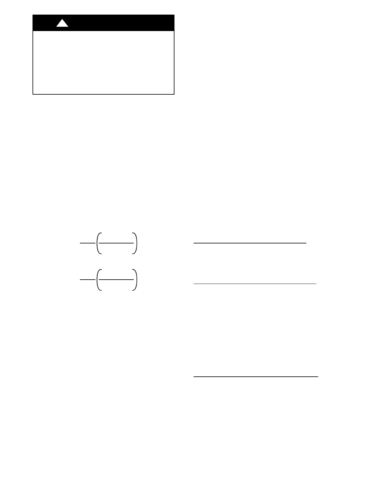
1. For other than fan--assisted appliances, such as a draft
hood-- equipped water heater:
Vo l u m e
Other
=
21ft
3
AC H
I
other
1000 Btu/hr
A04002
2. For fan--assisted appliances such as this furnace:
Vo l u m e
Fan
=
15ft
3
AC H
I
fan
1000 Btu/hr
A04003
If: Iother = combined input of all other than fan-- assisted appliances
in Btuh/hr
Ifan = combined input of all fan-- assisted appliances in Btuh/hr
ACH = air changes per hour (ACH shall not exceed 0.60.)
The following requirements apply to the Standard Method and to
the Known Air Infiltration Rate Method.
1. Adjoining rooms can be considered part of a space if:
a. There are no closeable doors between rooms.
b. Combining spaces on same floor level. Each opening shall
have free area of at least 1 in.
2
/1,000 Btuh (2,000mm
2
/kW)
of the total input rating of all gas appliances in the space,
but not less than 100 in.
2
(0.06 m
2
). One opening shall
commence within 12 in. (300 mm) of the ceiling and the
second opening shall commence within 12 in. (300 mm)
of the floor. The minimum dimension of air openings shall
be at least 3 in. (80 mm). See Fig. 7.
c. Combining space on different floor levels. The volumes of
spaces on different floor levels shall be considered as com-
municating spaces if connected by one or more permanent
openings in doors or floors having free area of at least 2
in.
2
/1,000 Btuh (4,400 mm
2
/kW) of total input rating of
all gas appliances.
2. An attic or crawlspace may be considered a space that freely
communicates with the outdoors provided there are ad-
equate permanent ventilation openings directly to outdoors
having free area of at least 1 -- in.
2
/4,000 Btuh of total input
rating for all gas appliances in the space.
3. In spaces that use the Indoor Combustion Air Method, in-
filtration should be adequate to provide air for combustion,
permanent ventilation and dilution of flue gases. However,
in buildings with unusually tight construction, additional air
MUST be provided using the methods described in the
Outdoor Combustion Air Method section.
4. Unusually tight construction is defined as Construction
with:
a. Walls and ceilings exposed to the outdoors have a continu-
ous, sealed vapor barrier. Openings are gasketed or sealed
and
b. Doors and openable windows are weatherstripped and
c. Other openings are caulked or sealed. These include joints
around window and door frames, between sole plates and
floors, between wall--ceiling joints, between wall panels,
at penetrations for plumbing, electrical and gas lines, etc.
Combination of Indoor and Outdoor Air
1. Indoor openings shall comply with the Indoor Combus-
tion Air Method below and,
2. Outdoor openings shall be located as required in the Out-
door Combustion Air Method mentioned previously and,
3. Outdoor openings shall be sized as follows:
a. Calculate the Ratio of all Indoor Space volume divided by
required volume for Indoor Combustion Air Method be-
low.
b. Outdoor opening size reduction Factor is 1 minus the Ra -
tio in a. above.
c. Minimum size of Outdoor openings shall be the size re-
quired in Outdoor Combustion Air Method above multi-
plied by reduction Factor in b. above. The minimum di-
mension of air openingsshallbenotlessthan 3 in. (80 mm).
CONDENSATE TRAP
Condensate Trap -- Upflow Orientation
When the furnace is installed in the upflow position, it is not
necessary to relocate the condensate trap or associated tubing.
Refer to Fig. 8 for upflow condensate trap information. Refer to
Condensate Drain section for information how to install the
condensate drain.
Condensate Trap -- Downflow Orientation.
When the furnace is installed in the downflow position, the
condensate trap will be initially located at the upper left corner of
the collector box, as received from the factory. See the top image
in Fig. 9. When the furnace is installed in the downflow
orientation, the condensate trap must be relocated for proper
condensate drainage. See the bottom image in Fig. 9.
To Relocate the Condensate Trap:
S Or i ent the furna ce in the downflow position.
S Fig. 9 shows the condens at e tra p and tubi ng bef or e and af te r
rel oca t ion. Re fe r to Fig. 9 to begi n the tr a p conve rs i on.
S Refe r to Condens ate Dra i n sect ion for inf orma ti on how to inst al l the
condens at e drain.
Condensate Trap -- Horizontal Orientation.
Whe n the furna ce is insta ll ed in the hori zont al right posit i on, the
condens at e trap will be initially located at the bottom of the collector
box, as received from the factory. See the top image in Fig. 10.
When the furnace is installed in the horizontal left position, the
condens at e trap will be initially located at the top of the collector box,
as received from the factory. See the top image in Fig. 11. In both
cas es the trap must be re posi ti oned on the col l ector box for proper
condens at e draina ge. See the bottom im age s in Fig. 10 and 11.
A field--supplied, accessory Horizontal Installation Kit (trap
grom met ) is re qui re d for al l direc t--vent hori zontal i nst al la t ions (only) .
The kit cont ai ns a rubbe r casi ng gromme t designe d to s e al betwe en
the furnac e casi ng and the condens at e tra p. See Fig. 18.

 Loading...

