19
A07227
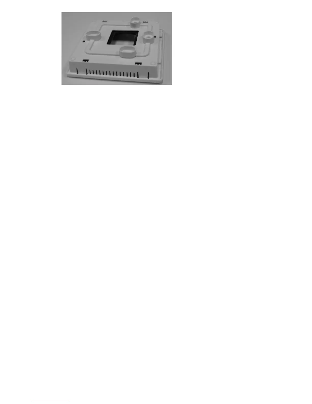
Fig. 13 -- Standoff
NOTE: Standoffs are provided as an aid when installing Equipment Control
Module on inside equipment or a solid wall.
12. Match and connect equipment wires to proper terminals of each connector
block being careful not to over tighten the screws. Correct polarity must be
observed when connecting the two wires from the Equipment Control Mod-
ule to the Thermidistat Control mounting base. If wires are connected incor-
rectly, the Display Module will not operate. See Fig. 8, 9 and 10.
13. Snap cover over top of Equipment Control Module. See Fig. 14.
 Loading...