27
For natural gas applications, gas pressure at unit gas connection
must not be less than 4 in. wg (996 Pa) or greater than 13 in. wg
(3240 Pa) while the unit is operating for sizes 07 to 14 and less
than 5 in. wg (996 Pa) or greater than 13 in. wg (3240 Pa) while
the unit is operating for size 16 (see Table 3). For liquefied petro-
leum applications, the gas pressure must not be less than 11 in. wg
(2740 Pa) or greater than 13.0 in. wg (3240 Pa) at the unit connec-
tion (see Table 4).
Table 3 — Natural Gas Supply Line Pressure Ranges
Table 4 — Liquid Propane Supply Line
Pressure Ranges
The gas supply pipe enters the unit at the burner access panel on
the front side of the unit through the long slot at the bottom of the
access panel. The gas connection to the unit is made to the
1
/
2
-in.
FPT gas inlet port on the unit gas valve for sizes 07-14 and
3
/
4
-in.
FPT gas inlet port on the unit gas valve for size 16 (see Table 5).
Manifold pressure is factory-adjusted for NG fuel use. Adjust as
required to obtain best flame characteristics.
Table 5 — Natural Gas Manifold Pressure Ranges
Manifold pressure for LP fuel use must be adjusted to specified
range (see Table 6). Follow instructions in the accessory kit to
make initial readjustment.
Table 6 — Liquid Propane Manifold Pressure Ranges
Install a gas supply line that runs to the unit heating section. Refer
to the NFPA 54/NFGC or equivalent code for gas pipe sizing data.
Do not use a pipe size smaller than
1
/
2
-inch. Size the gas supply
line to allow for a maximum pressure drop of 0.5 in. wg (124 Pa)
between gas regulator source and unit gas valve connection when
unit is operating at high-fire flow rate.
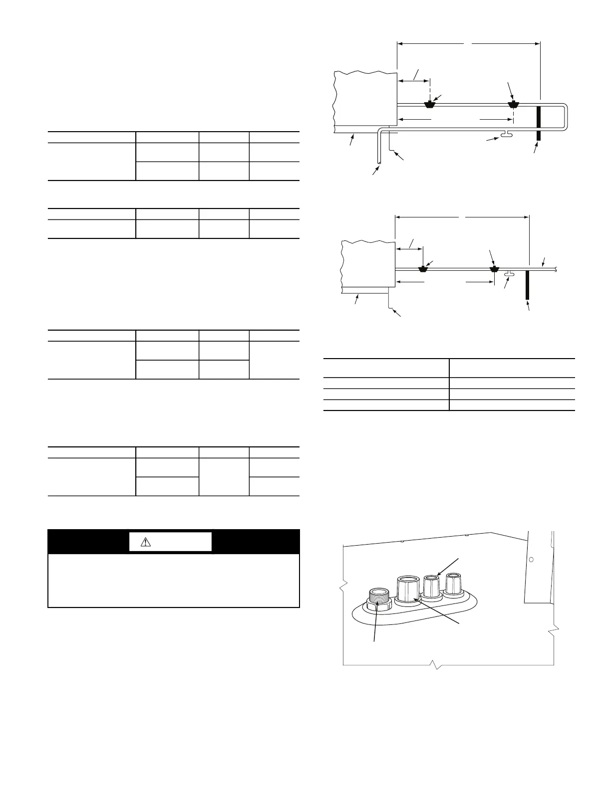
The gas supply line can approach the unit in three ways: horizon-
tally from outside the unit (across the roof), thru-curb/under unit
basepan (accessory kit required) or through unit basepan (factory-
option or accessory kit required). Consult accessory kit installation
instructions for details on these installation methods. Observe
clearance to gas line components per Fig. 32.
Fig. 32 — Gas Piping Guide (with Accessory Thru-
the-Curb Service Connections)
FACTORY-OPTION THRU-BASE CONNECTIONS (GAS
CONNECTIONS) (SIZES 07-14)
This service connection kit consists of a
1
/
2
-in. NPT gas adapter
fitting (brass), a
1
/
2
-in. electrical bulkhead connector and a
3
/
4
-in.
electrical bulkhead connector, all factory-installed in the embossed
(raised) section of the unit basepan in the condenser section. See
Fig. 33 and 34.
Fig. 33 — Thru-Base Connection Fittings
(Size 08-16 units and 07 units built prior to 4/15/2019)
UNIT MODEL UNIT SIZE MIN. MAX.
48TCD/E/F/S/R/T
07, 08, 09, 12,
14
4.0 in. wg
(996 Pa)
13.0 in. wg
(3240 Pa)
16
5.0 in. wg
(1250 Pa)
13.0 in. wg
(3240 Pa)
UNIT MODEL UNIT SIZE MIN. MAX.
48TCD/E/F/S/R/T
07, 08, 09, 12,
14, 16
11.0 in. wg
(2740 Pa)
13.0 in. wg
(3240 Pa)
UNIT MODEL UNIT SIZE HIGH FIRE LOW FIRE*
48TCD/E/F/S/R/T
07, 08, 09,
12, 14
3.5 in. wg
(872 Pa)
2.0 in. wg
(498 Pa)
16
3.0 in. wg
(747 Pa)
* LOW FIRE, 1.7 in. wg (423 P
a), applies to the following units only:
48TCD/E/F*08 and 48TCD*09.
UNIT MODEL UNIT SIZE HIGH FIRE LOW FIRE*
48TCD/E/F/S/R/T
07, 08, 09,
12, 14
10.0 in. wg
(2490 Pa)
5.7 in. wg
(1420 Pa)
16
6.6 in. wg
(1644 Pa)
* LOW FIRE, 5.0 in. wg (1420 Pa), applies to the following units only:
48TCD/E/F*08 and 48TCD*09.
CAUTION
EQUIPMENT DAMAGE
Failure to follow this caution may result in equipment damage.
When connecting the gas line to the unit gas valve, the installer
MUST use a backup wrench to prevent damage to the valve.
X
BASE UNIT
BASE RAIL
ROOF
CURB
9” MINIMUM CLEARANCE
FOR PANEL REMOVAL
MANUAL GAS
SHUTOFF VALVE*
GAS
REGULATOR*
48” MINIMUM
DRIP LEG
PER NFGC*
FIELD-FABRICATED
SUPPORT*
FROM
GAS
METER
X
BASE UNIT
BASE RAIL
ROOF
CURB
9” MINIMUM CLEARANCE
FOR PANEL REMOVAL
MANUAL GAS
SHUTOFF VALVE
*
GAS
REGULATOR
*
48” MINIMUM
DRIP LEG
PER NFGC
*
FIELD-
FABRICATED
SUPPORT
FROM
GAS
METE
R
6 TO 12.5 TON UNITS
15 TON UNIT
* Field-supplied.
STEEL PIPE NOMINAL
DIAMETER (in.)
SPACING OF SUPPORTS X
DIMENSION (ft)
1
/
2
6
3
/
4
or 1 8
1
1
/
4
or larger 10
LOW VOLTAGE
CONDUIT
CONNECTOR
HIGH VOLTAGE
CONDUIT
CONNECTOR
BRASS FITTING FOR 3 TO 6 TON UNITS.
 Loading...


