52
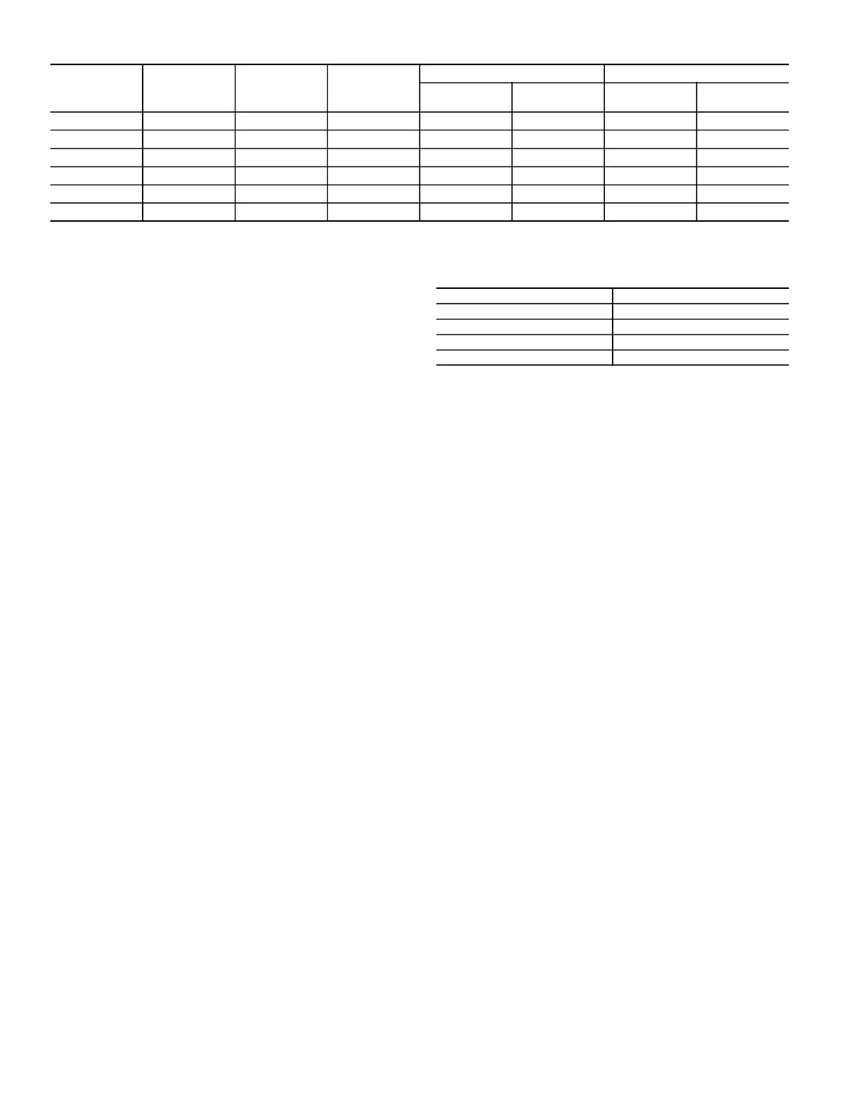
Table 22 — Single Enthalpy and Dual Enthalpy High Limit Curves
ENTHALPY SETTINGS
When the OA temperature, enthalpy and dew point are below the
respective set points, the Outdoor Air can be used for economiz-
ing. Figure 77 shows the new single enthalpy boundaries in the
W7220. There are 5 boundaries (set points ES1 through ES5),
which are defined by dry bulb temperature, enthalpy and dew
point.
Refer to Table 22 for ENTH CURVE set point values.
The W7220 calculates the enthalpy and dew point using the OA
temperature and humidity input from the OA enthalpy sensor.
When the OA temperature, OA humidity and OA dew point are
all below the selected boundary, the economizer sets the econo-
mizing mode to YES, economizing is available.
When all of the OA conditions are above the selected boundary,
the conditions are not good to economize and the mode is set to
NO.
Figure 77 shows the 5 current boundaries. There is also a high lim-
it boundary for differential enthalpy. The high limit boundary is
ES1 when there are no stages of mechanical cooling energized and
HL (high limit) when a compressor stage is energized.
Table 22 provides the values for each boundary limit.
TWO-SPEED FAN OPERATION
The W7220 controller has the capability to work with a system us-
ing a 2-speed supply fan. The W7220 does not control the supply
directly but uses the following input status to determine the speed
of the supply fan and controls the OA damper to the required posi-
tion (see Table 23).
Table 23 — Fan Speed
The W (heating mode) is not controlled by the W7220 but it re-
quires the status to know where to position the OA damper for
minimum position for the fan speed.
The 2-speed fan delay is available when the system is pro-
grammed for 2-speed fan (in the System Setup menu item). The 2-
speed fan delay is 5 minutes by default and can be changed in the
Advanced Setup menu item. When the unit has a call for Y1 In
and in the free cooling mode there is a call for Y2 In, the 2-speed
fan delay starts, the OA damper will modulate 100% open, and the
supply fan should be set to high speed by the unit controller.
After the delay, one of two actions will happen:
• The Y2 In call will be satisfied with the damper 100%
open and fan on high speed and the call will turn off.
OR
• If the call for additional cooling in the space has not been
satisfied, then the first stage of mechanical cooling will be
enabled through Y1 Out or Y2 Out.
ENTHALPY
CURVE
TEMP. DRY
BULB (°
F)
TEMP.
DEWPOINT (
°
F)
ENTHALPY
(btu/lb/da)
POINT P1 POINT P2
TEMP. (
°
F)
HUMIDITY
(%RH)
TEMP. (
°
F)
HUMIDITY
(%RH)
ES1 80 60 28.0 80 36.8 66.3 80.1
ES2 75 57 26.0 75 39.6 63.3 80.0
ES3 70 54 24.0 70 42.3 59.7 81.4
ES4 65 51 22.0 65 44.8 55.7 84.2
ES5 60 48 20.0 60 46.9 51.3 88.5
HL 86 66 32.4 86 38.9 72.4 80.
3
STATE FAN SPEED
OCC Low
Y1 Low
Y2 High
W High
 Loading...


