ROUBLESHOOTING
T
16
208743 Rev. 1
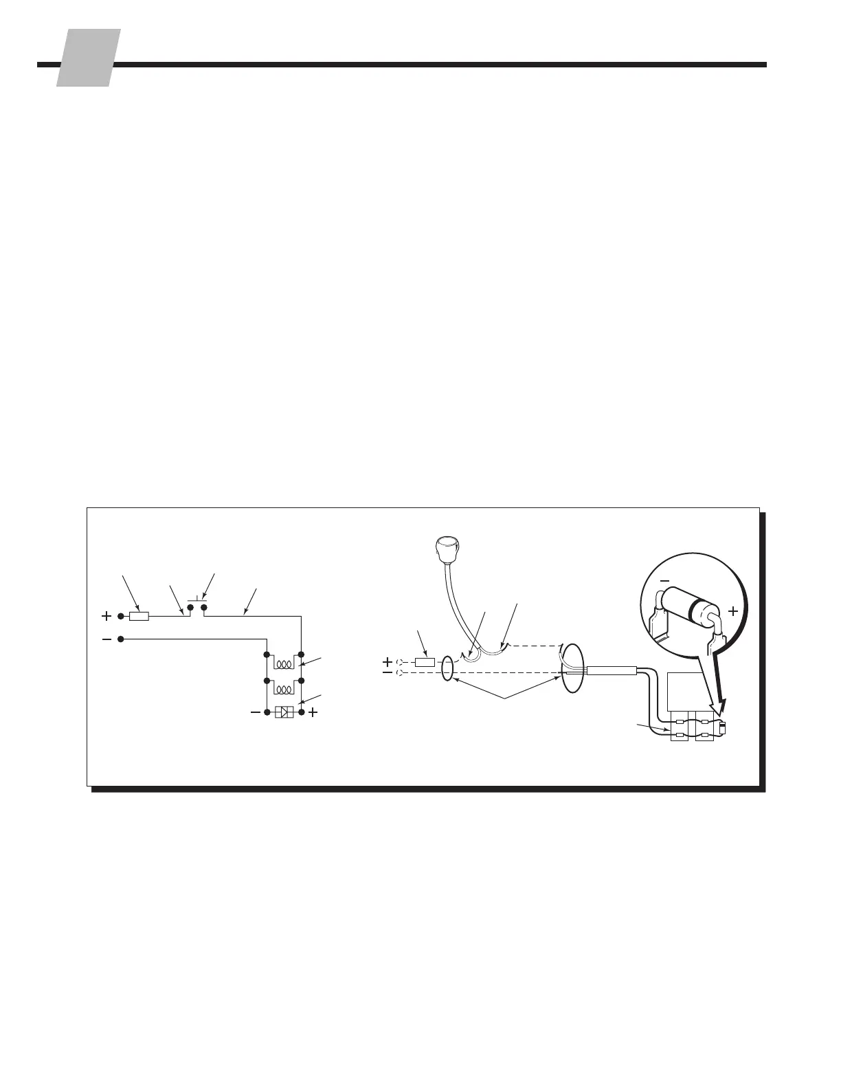
4.5 Electrical Circuit
(Solenoid equipped attachments)
1 Check for truck voltage at the solenoid coil terminals
when the knob button is pushed.
2 Check the solenoid coil to make sure it matches
the truck voltage. The coil voltage is marked at the
terminals. Test the coils by checking for resistance with
a Volt Ohm Meter across the terminals with the wires
disconnected.
• If there is no ohmmeter reading shown, the solenoid
coil is defective and requires replacing.
3 Check the control knob circuit fuse. Replace if
necessary.
4 Check for loose electrical connections at the truck
ignition switch, control knob button(s), solenoid valve
terminals and diodes.
5 Remove the diode(s) from the solenoid valve terminals.
Test with an ohmmeter for high resistance in one
direction and no resistance in the other direction. If
there is no resistance in both directions, replace the
diode.
Diode
Black
White
7.5 Amp
Fuse
User
Supplied
Wire
Solenoid
Valves
White
Black
Knob
Button
7.5 Amp
Fuse
Diode
Solenoid
Valves
18 Gauge Wire
1/4 in. Terminals
 Loading...