208743 Rev. 1
NSTALLATION
I
2
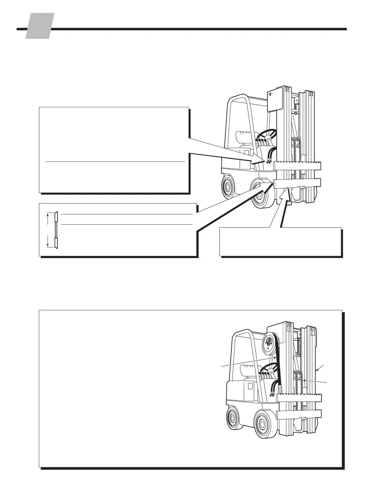
2.1 Truck System
Requirements
2.2 Recommended
Hydraulic Supply
Fork Positioner with Standard Valve
Non-Sideshifting
A Mast Single Internal Reeving
OR
B RH THINLINE 2-Port Hose Reel Group
Sideshifting
A Mast Double Internal Reeving
OR
A and B Mast Single Internal Reeving and
RH THINLINE 2-Port Hose Reel Group
OR
B and C RH and LH THINLINE 2-Port Hose Reel Groups
Fork Positioner with Sequence Valve
A Mast Single Internal Reeving
OR
B RH THINLINE 2-Port Hose Reel Group
Fork Positioner with Solenoid Valve
A and B Mast Single Internal Reeving and RH Cable Reel Group
OR
B RH 6-N-1 Cable/Hose Reel Group
Clean carriage bars and inspect for
damaged notches.
Truck Relief Setting
Minimum – 2300 psi (160) bar
Maximum – 2600 psi (180) bar
Truck Flow Volume
55F 100F/120F
Minimum 3 GPM (11 L/min.) 4 GPM (15 L/min.)
Recommended 4 GPM (15 L/min.) 5 GPM (19 L/min.)
Maximum 5 GPM (19 L/min.) 6 GPM (23 L/min.)
Dimension A − ITA (ISO)
Mounting Minimum Maximum
Class II
14.94 in. (380.0 mm)
15.00 in. (381.0 mm)
Class III
18.68 in. (474.5 mm) 18.74 in. (476.0 mm)
Class IV
23.44 in. (595.5 mm) 23.50 in. (597.0 mm)
 Loading...