— 8 —
7. CIRCUIT EXPLANATIONS
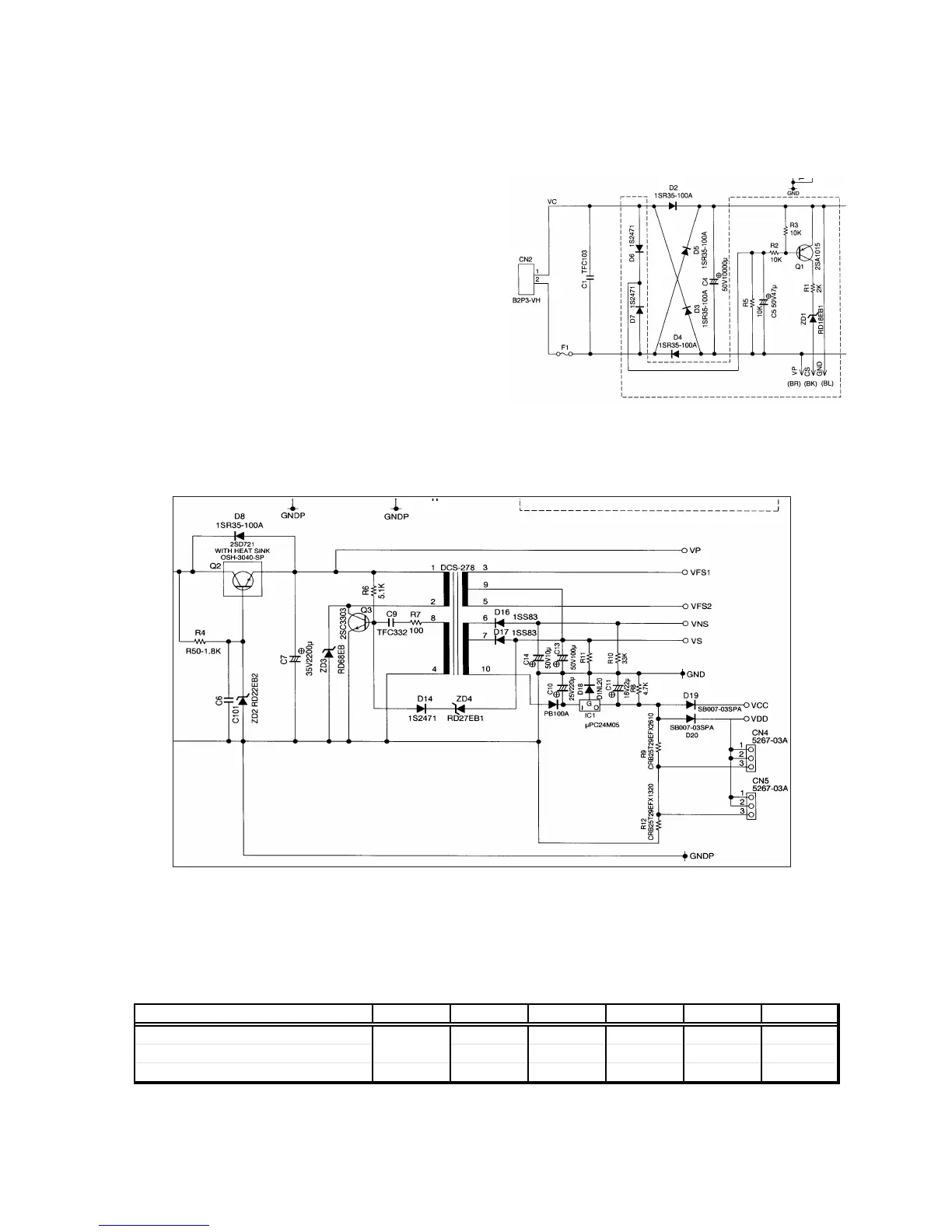
7-1. Power supply circuit
1) Diodes rectification bridge
By diodes rectification bridge, alternating
voltage is converted into DC voltage, and the
electrical voltage is done filtering of by
Capacitor C4.
2) Power supply circuit for B-6
The electrical voltage which puts in resistor 3
when line voltage includes anomaly changes,
and transistor Q1 becomes on status, and
CS signal is done outgoing of by this, and VP
is supplied than Power supply B-6.
Note: The component for connection isn’t equipped with in plant shipping.
(service arrangement)
7-2. DC/DC converter circuit
2SD721(Q2) is Power voltage control transistor, and electric power supply is supplied in DC-
DC converter with 2SC3303(Q3). 2SC3303(Q3) does a work as oscillator. The frequency of
2SC3303(Q3) is controlled by signal done feed back of through RD27EB1.
7-3. Electrical voltage value in check point
Vc Vp Vcc/Vdd Vns Vs Vf
Rated output electrical voltage Min: 23 V 20 V 5 V 32 V 27 V 4.75 V
Output volta
e drift ran
e Max: 42 V 2 V 0.3 V 10% 10% 7%
Output voltage drift range AC DC DC DC DC AC

 Loading...