Figures
1 to
3
showed the kind
of reading
phase
angle distortion
pattern
that
occurs when
the
phase angle reading
speed from
0 to it is accelerated
while
the
phase
angle
reading
speed from
7r to
2
7r
is
slowed
down. A pattern
such
as this is created
when
the
saw-tooth
wave form
is
selected
with
the DCO Wave Form
parameter.
If
a
different
kind of wave form
is selected
with the DCO
Wave Form
parameter,
the
reading
phase
angle is distorted
to
that respective
pattern. The
CZ-
1000
can thus
output
a
whole
variety
of wave
forms.
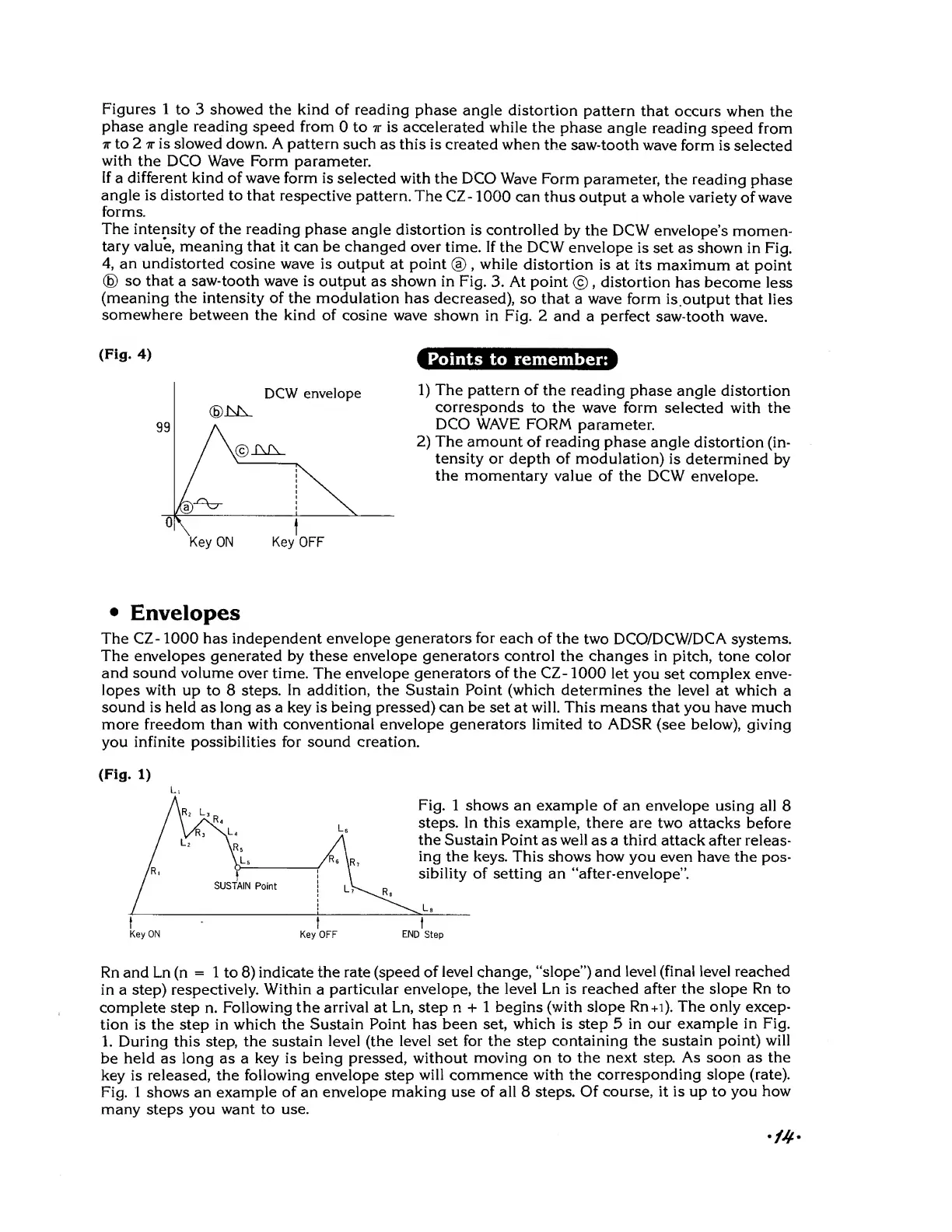
The intensity of the reading
phase angle distortion
is
controlled by
the DCW envelope's
momen-
tary value, meaning
that
it can be changed
over time. If
the DCW
envelope
is
set as shown in Fig.
4,
an undistorted
cosine wave is
output at point
®
,
while
distortion is
at its maximum
at point
©
so that
a
saw-tooth
wave is
output as shown in Fig.
3. At point
©
,
distortion
has become less
(meaning the intensity of the modulation
has
decreased),
so that
a
wave
form
is
output that lies
somewhere
between the kind
of
cosine wave shown
in Fig. 2
and
a
perfect saw-tooth
wave.
(Fig.
4)
Points
to remember:
DCW
envelope
Key
ON
Key
OFF
1)
The pattern of
the reading
phase
angle distortion
corresponds
to
the
wave form selected
with the
DCO WAVE FORM
parameter.
2)
The
amount
of reading
phase angle
distortion (in-
tensity or
depth of modulation)
is
determined by
the
momentary
value of the DCW envelope.
•
Envelopes
The CZ
-
1000
has independent envelope
generators
for
each of
the
two
DCO/DCW/DCA
systems.
The envelopes generated
by
these envelope
generators
control the changes in
pitch, tone
color
and
sound
volume
over time.
The envelope
generators
of
the CZ
-
1000 let
you set complex
enve-
lopes
with
up to 8
steps.
In addition,
the
Sustain Point (which determines
the
level at which
a
sound is
held as long as a key is being pressed) can be set
at
will. This means that you have
much
more freedom than
with conventional envelope generators limited to ADSR
(see
below),
giving
you
infinite possibilities for sound creation.
(Fig.
1)
Fig.
1 shows an example of an envelope
using all
8
steps. In this example, there are
two attacks
before
the Sustain Point
as
well
as a third attack after releas-
ing
the keys. This shows how
you
even
have the
pos-
sibility
of setting an "after-envelope".
Key ON
Key OFF
END
Step
Rn and Ln (n
=
1
to
8)
indicate
the rate (speed
of level change, "slope") and
level (final level
reached
in a step)
respectively.
Within
a
particular
envelope, the level Ln is
reached after the slope
Rn
to
complete step n.
Following the arrival at Ln, step n
+
1 begins (with slope
Rn+i). The only excep-
tion is the step in which
the Sustain
Point has been set,
which is step
5
in our
example in Fig.
1.
During this step, the
sustain level (the level set
for the
step
containing
the sustain point) will
be held as long as a
key is being pressed, without
moving on to the
next
step.
As soon as the
key is released,
the following envelope
step
will commence with the
corresponding slope (rate).
Fig. 1
shows an
example of an envelope
making use of all 8 steps.
Of
course, it is up to you
how
many
steps you
want to use.
 Loading...