To replace the chassis cover, place the cover evenly on the top of the device and use the screws to secure it
to the device.
Note
Replacing the Power Supply
These are the steps to replace the power supply:
1. Disconnect the power cord from the power supply.
2. Remove the bezel. The bezel is secured with snap latches. To remove the bezel, hold the top and bottom,
and pull the bezel.
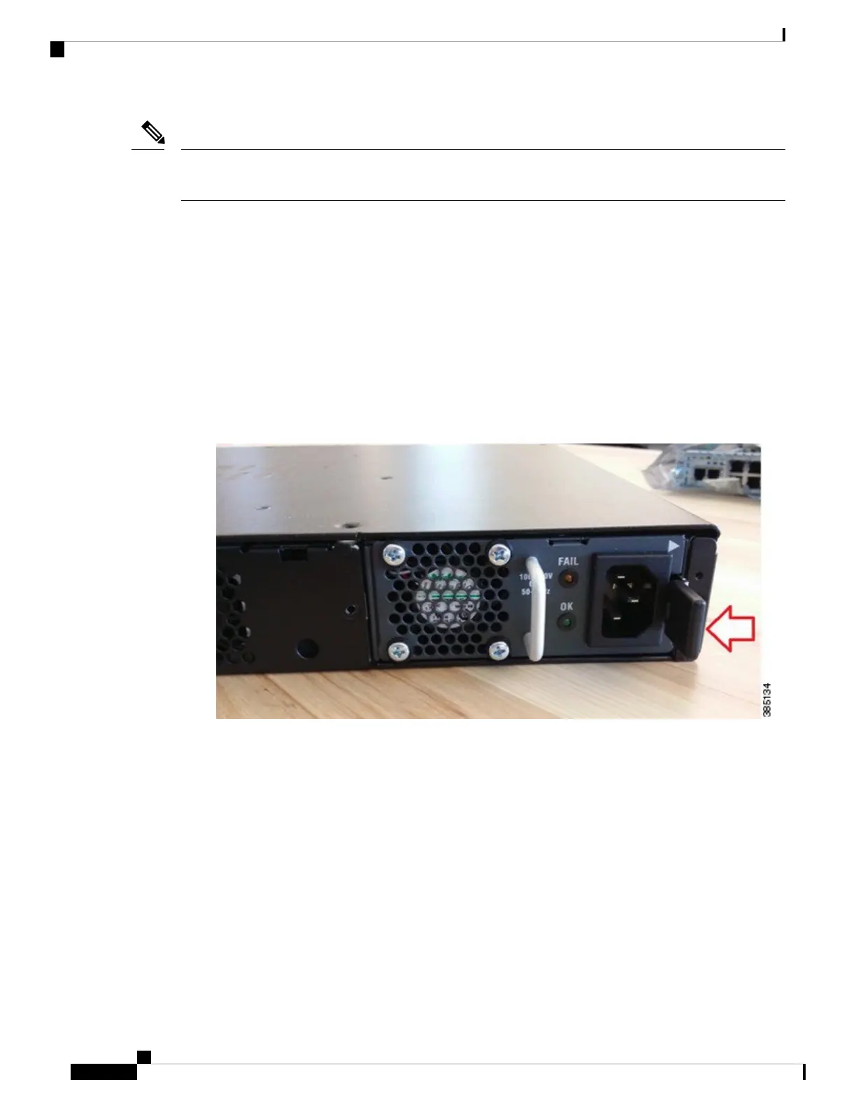
3. The latch that secures the power supply to the device is on the right. Press the latch to the left and pull
out the power supply using the handle.
Figure 11: Power Supply Latch and Handle
4. Insert the replacement power supply.
5. Replace the bezel.
Installing Drive Bays
There are two drive bays. You can use one of them, both of them, or none. Refer to Hardware Features -
Replaceable and Upgradable Units, on page 12 to know the types of storage module that each of this bay can
hold. If you had not ordered drives, the slots are closed with a blank cover as shown in the image.
These are the steps to install a drive in a drive bay:
1. The drive bays are in the front panel of the device. The bays are closed with a cover if there are no drives
in the slots.
Cisco 5400 Enterprise Network Compute System Hardware Installation Guide
30
Installing and Upgrading FRUs
Replacing the Power Supply