1-88
Cisco Integrated Services Router Hardware Installation Guide
Chapter 1 Product Overview
Cisco 860, 880, 890 Series
Cisco C898EAG-LTE Integrated Service Router
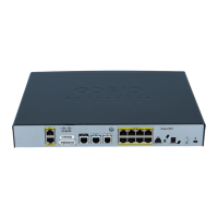
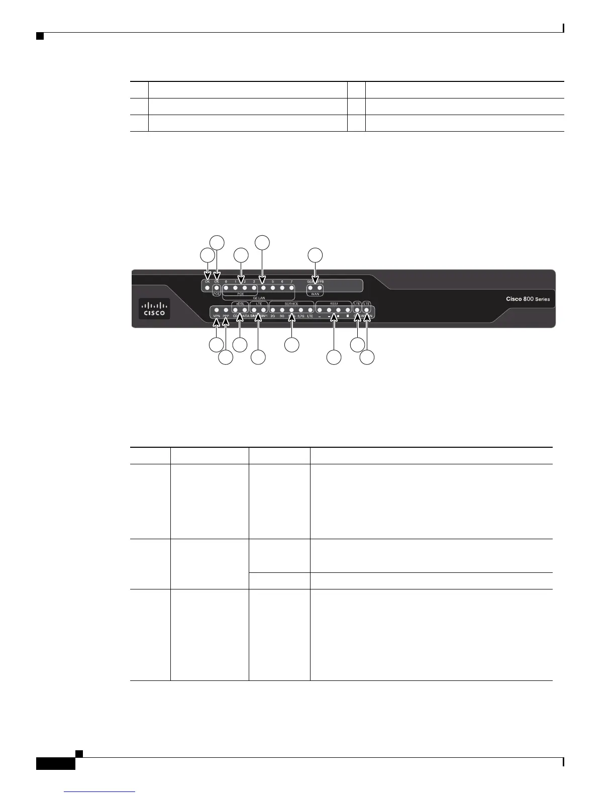
Figure 1-52 shows the front panel of the Cisco C898EAG-LTE ISR.
Figure 1-52 Front Panel of the Cisco C898EAG-LTE ISR
Table 1-36 describes the LEDs for the Cisco C898EAG-LTE ISR.
6 8-port Gigabit Ethernet switch 14 Active GPS antenna connector
7 Console/Auxiliary port 15 VDSL or ADSL over POTS
8 Power connector 16 4G antenna connector—M0/MAIN
Table 1-36 LED Descriptions for the Cisco C898EAG-LTE ISR
Number LED Color Description
1 Power OK Green On—DC power is being supplied to the router and the
Cisco IOS software is running.
Blinking—Boot up is in process, or the router is in
ROMMON mode.
Off—Power is not supplied to the router.
2 PoE Green On—PoE is connected and powered.
Off—PoE is not installed.
Amber On—Fault with the PoE.
3 GE LAN PoE
Ports
Green/Ambe
r
Amber On—Ethernet port is connected.
Amber On—Fault with PoE. There is a fault with the
in-line power supply.
Green/Amber Blinking—Data is either being received or
transmitted.
Green/Amber Off—Ethernet port is not connected.
 Loading...