e) Attach the second slide-rail assembly to the opposite side of the rack. Ensure that the two slide-rail assemblies are at
the same height and are level front-to-back.
f) Pull the inner slide rails on each assembly out toward the rack front until they hit the internal stops and lock in place.
Step 4 Insert the server into the slide rails:
This server can weigh up to 64 pounds (29 kilograms) when fully loaded with components. We recommend
that you use a minimum of two people or a mechanical lift when lifting the server. Attempting this procedure
alone could result in personal injury or equipment damage.
Caution
a) Align the rear ends of the inner rails that are attached to the server sides with the front ends of the empty slide rails
on the rack.
b) Push the inner rails into the slide rails on the rack until they stop at the internal stops.
c) Slide the inner-rail release clip toward the rear on both inner rails, and then continue pushing the server into the rack
until its front slam-latches engage with the rack posts.
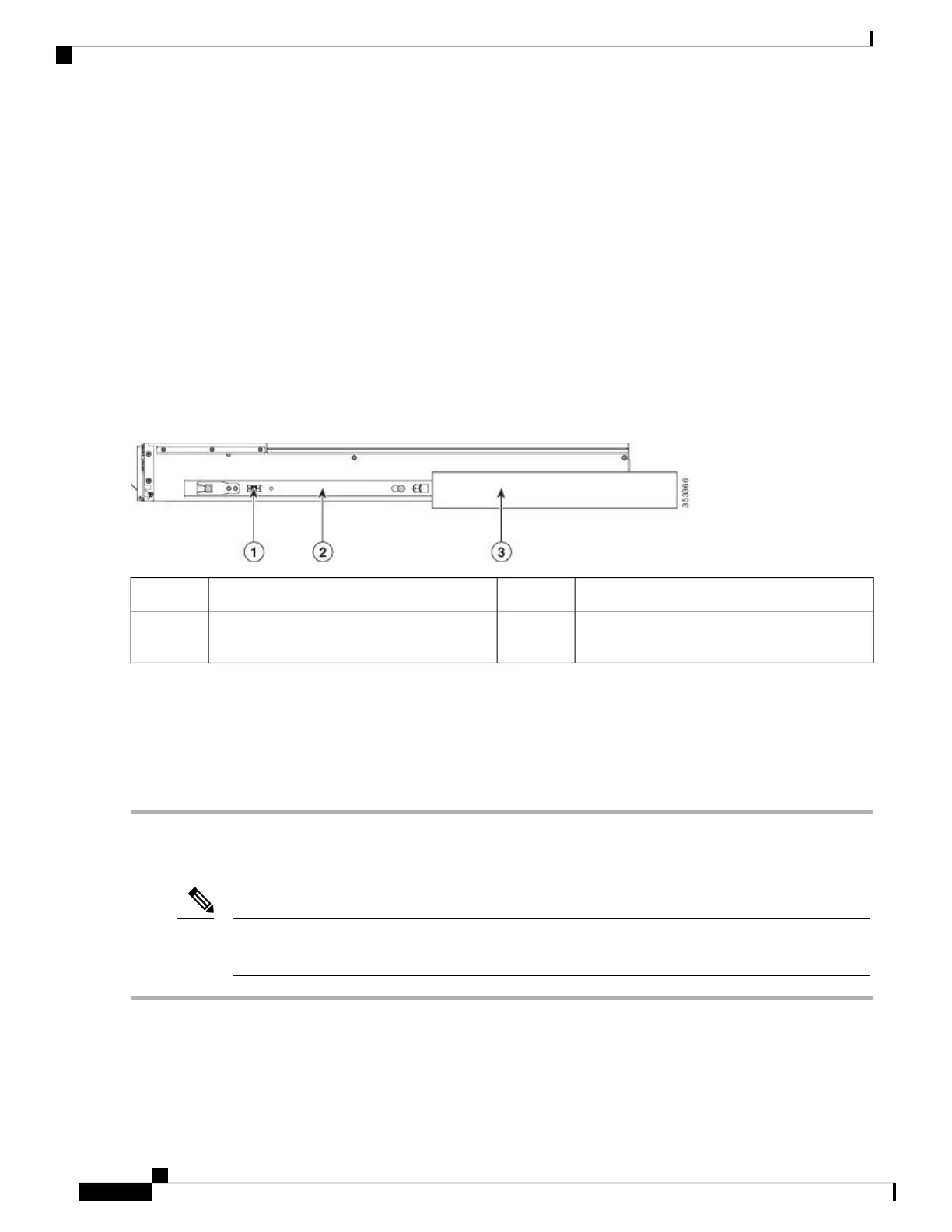
Figure 10: Inner-Rail Release Clip
Outer slide rail attached to rack post3Inner-rail release clip1
-Inner rail attached to server and inserted into
outer slide rail
2
Step 5 (Optional) Secure the server in the rack more permanently by using the two screws that are provided with the slide rails.
Perform this step if you plan to move the rack with servers installed.
With the server fully pushed into the slide rails, open a hinged slam latch lever on the front of the server and insert a
screw through the hole that is under the lever. The screw threads into the static part of the rail on the rack post and prevents
the server from being pulled out. Repeat for the opposite slam latch.
Installing the Cable Management Arm (Optional)
The cable management arm (CMA) is reversible left-to-right. To reverse the CMA, see Reversing the
Cable Management Arm (Optional), on page 25 before installation.
Note
Step 1 With the server pushed fully into the rack, slide the CMA tab of the CMA arm that is farthest from the server onto the
end of the stationary slide rail that is attached to the rack post. Slide the tab over the end of the rail until it clicks and
locks.
Cisco APIC M4/L4 Server Installation and Service Guide
24
Installing the Server
Installing the Cable Management Arm (Optional)
 Loading...