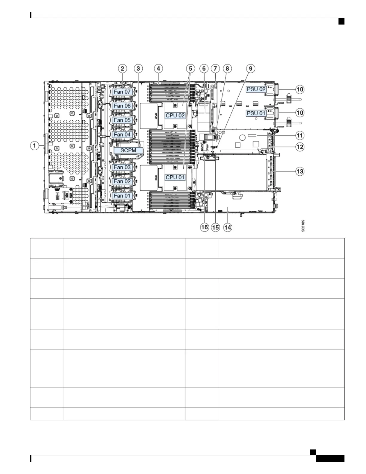
Figure 13: Cisco APIC M3 and L3 Server, Serviceable Component Locations
RTC battery, vertical socket9Front-loading drive bays 1–10 support SAS/SATA
drives.
1
Power supplies (hot-swappable when redundant as
1+1)
10Cooling fan modules (seven, hot-swappable)2
Trusted platform module (TPM) socket on
motherboard (not visible in this view)
11Supercap unit mounting bracket (RAID backup)3
PCIe riser 1/slot 1 (half-height, x16 lane)
Includes PCIe cable connectors for front-loading
NVMe SSDs (x8 lane)
12DIMM sockets on motherboard (12 per CPU)4
VIC 1455 with external 10/25-Gigabit Ethernet ports
(4)
13CPUs and heatsinks (up to two)5
Available (empty) PCIe slot14Mini storage module socket
Supports either an SD card module with two SD
card slots; or an M.2 module with two NVMe or
SATA M.2 SSD slots.
6
PCIe cable connectors for front-loading NVMe SSDs
on PCIe riser 2
15Chassis intrusion switch (optional)7
Micro-SD card socket on PCIe riser 116Internal USB 3.0 port on motherboard8
Cisco APIC M3/L3 Server Installation and Service Guide
33
Maintaining the Server
Serviceable Component Locations
 Loading...