20
Connecting +24V DC Power to the Cisco ASR 1002-X Router
The +24V DC power supply uses a spring-loaded terminal block. The input terminal block requires 8 AWG multi-strand wiring
to support input current. Features are provide for strain relieving the input wires from the terminal block on the front panel.
The recommended branch circuit breaker for the Cisco ASR 1002-X Router +24V DC power supply is a 40Amp UL listed circuit
breaker.
Before you begin, read these important notices about the +24V DC power supply:
• The labeling displays +27V DC INPUT. This labeling describes the nominal voltage provided at a cell site.
• Observe the polarity location—Unlike the polarity labels of the –48V DC power supply (ground, positive, negative), the
polarity labels on the +24V DC are ground, negative, positive as shown in Figure 16 from right to left as they appear on
the actual power supply unit.
• The ground (GND) lead is always installed first and removed last.
• The +24V DC power supply uses a spring loaded terminal block; therefore have the recommended screwdriver size
available.
• Review the diagrams to see how the wire is stripped and how the screwdriver is inserted at an angle into the terminal block.
• Have the following equipment available to install and remove the +24V DC power supply:
–
Phoenix-Contact 3.5mm flat-blade screwdriver or equivalent
–
Wire-stripping tool for stripping 8-gauge wire
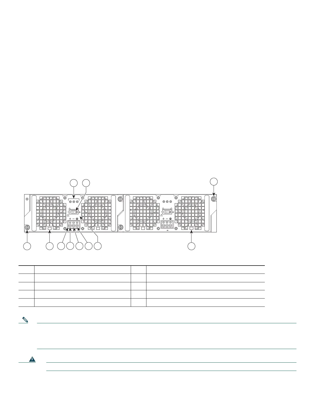
Figure 16 Cisco ASR 1002-X Router +24V DC Power Supply Components
Note The color coding of the +24V DC-input power supply leads depends on the color coding of the +24V DC power source
at your site. Typically, green or green/yellow is used for ground. Make certain the lead color coding you choose for the
+24V DC-input power supply matches lead color coding used at the +24V DC power source. Most commonly used wire
color-coding is red for positive (+) lead and black for negative (–) lead.
Warning
When you install the unit, the ground connection must always be made first and disconnected last.
Statement 1046
1 +24V DC terminal block 6 Standby/On switch
2 Positive (+) lead 7 Captive fastener
3 Negative (-) lead 8 Power supply tabs
4 Earth ground (GND) lead 9 +27V DC INPUT label
5 Power supply LEDs
OUTPUT INPUT
FAI L
OK OK
FAN
+27V 32A
This unit might have more than
one power supply connection.
All connections must be removed
to de-energize the unit.
+27V DC INPUT
OUTPUT INPUT
FAI L
OK OK
FAN
+27V 32A
This unit might have more than
one power supply connection.
All connections must be removed
to de-energize the unit.
+27V DC INPUT
2
31
5 6
0
1
7
4
7
8
253164
8
9

 Loading...


