25
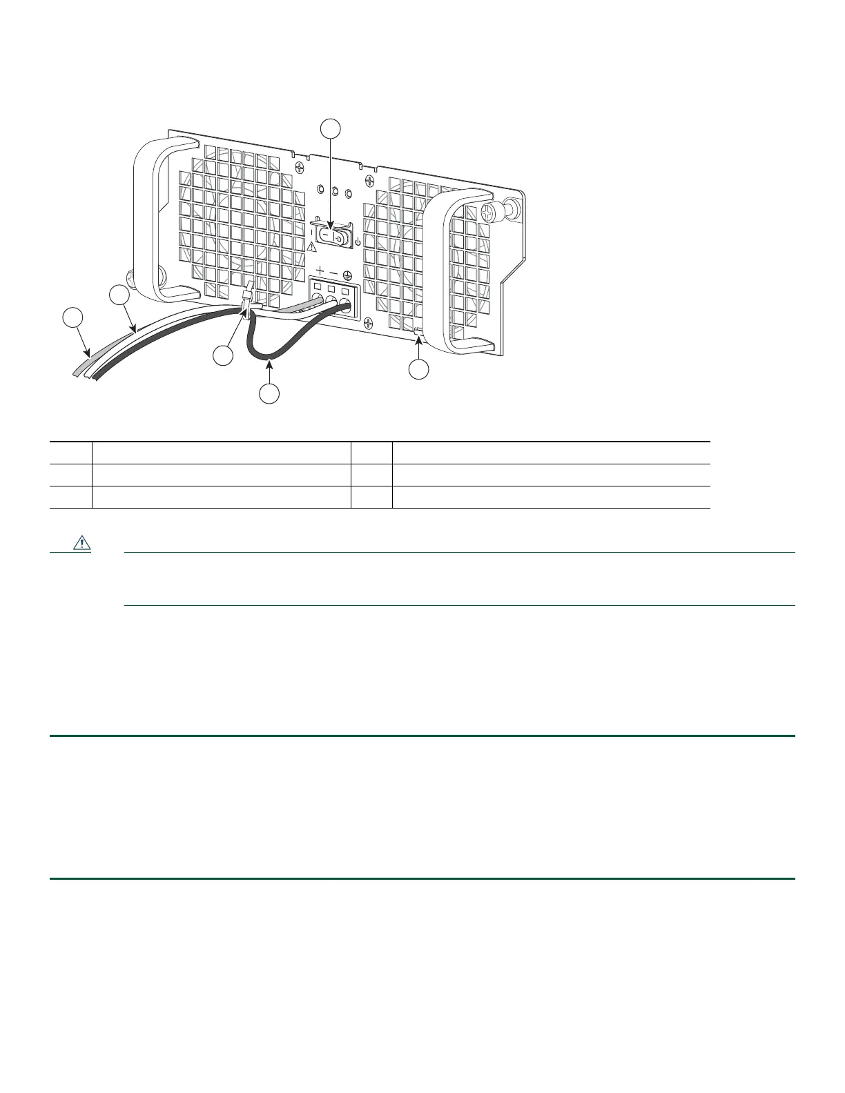
Figure 23 Cisco +24V DC Power Supply Terminal Block Ground Lead Service Loop
Caution When securing the ground, positive, and negative +24V DC-input leads to the power supply faceplate, leave extra
service loop in the ground (GND) lead to ensure that the ground lead is the last lead wire to disconnect from the
power supply if a great deal of strain is placed on all three leads.
Step 11 After tightening the receptacle screw for the ground, and leaving the extra service loop in the ground lead, use a cable
tie to secure the three leads to the power supply faceplate tie-wrap tab as shown in.
Step 12 Turn on the branch source breaker. The following LEDs light up: OUTPUT FAIL is red, INPUT OK should be green,
and FAN OK is off.
Step 13 Place the power supply standby switch to the On (|) position.
The power supply LEDs light when power is supplied to
the router. The following LEDs light up: OUTPUT FAIL is off, INPUT OK is green, and FAN OK is green
.
This completes the steps for connecting the +24V DC power supply in the Cisco ASR 1002-X Router.
Verifying Power Supply operation
Follow this procedure to verify power supply is operating correctly.
Step 1 Check that the power supply LEDs are:
–
INPUT OK is green
–
FAN OK is green
–
OUTPUT FAILED is not illuminated
Step 2 To ensure that the power supply state is OK, type the show platform command. This output sample is from a Cisco
ASR1002-X router. The other Cisco ASR1000 routers display similar type of output.
1 Earth ground lead wire with service loop 4 +24V DC power supply Standby switch
2 Negative lead wire 5 Power supply tabs
3 Positive lead wire
OUTPUT INPUT
FAI L
OK OK
FAN
This unit might have more than
one power supply connection.
All connections must be removed
to de-energize the unit.
+27V DC INPUT
+27V 32A
253171
3
1
4
2
5
5

 Loading...


