2-7
Cisco ASR 9000 Series Aggregation Services Router Overview and Reference Guide
OL-17501-09
Chapter 2 Functional Description
Route Switch Processor Card
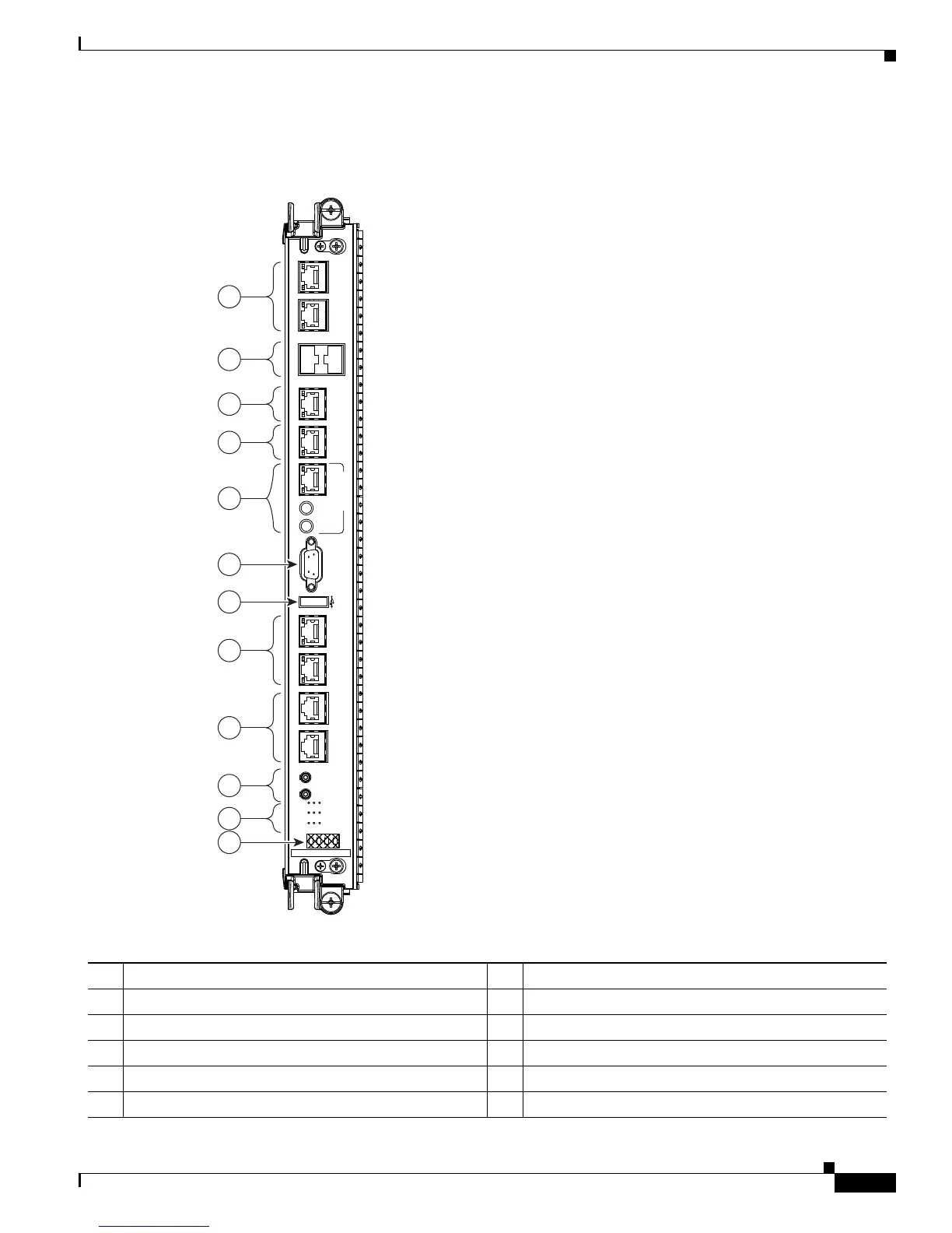
Figure 2-7 shows the front panel of the RSP-440 card.
Figure 2-7 RSP-440 Card Front Panel
330841
SYNC 0 SYNC 1
SFP + 0
SFP + 1
IEEE 1588 ICS0
A9K-RSP440-SE
BITS J211 BITS J211
LINK ACT
ALARM OUT
ACO
LAMP
TEST
AUX
CONSOLEMGT LAN 1
BITS J.211
MGT LAN 0
BITS J.211
10MHz 1PPS
FC FAULT
MAJ
ACO
SSD
CRIT
FAIL
GPS
MIN
SYNC
GPS INTERFACE
ICS1/TOD
6
7
12
1
8
9
11
10
2
3
4
5
1 SYNC (BITS/J.211) ports 7 External USB port
2 SFP ports 8 Management LAN ports
3 IEEE 1588 port 9 CONSOLE and AUX ports
4 ToD port 10 Alarm Cutoff (ACO) and LAMP TEST push buttons
5 10MHz and 1PPS indicators 11 Eight discrete LED indicators
6 Alarm Out DB9 connector 12 LED matrix display

 Loading...


