Hinge bracket2Card cage door1
Step 2 Attach the left and right hinge brackets to the chassis using three screws (M4 thread) for each bracket. Tighten
the screws to a torque of 11 in-lb (1.20 N-m). The L-shaped brackets should align with the holes in the cable
management tray from which you removed the screws.
Step 3 Secure the L-shaped brackets to the chassis and cable management tray by re-inserting and tightening the
cable management tray screws you removed.
Step 4 Align the exhaust air deflector at the rear of the chassis behind the top fan tray outlets (see the below figure),
and use a screwdriver to tighten the two screws, one on each side of the deflector. The deflector’s measurements
are width 17.48” x height 4.72” x depth 5.21” and deflects the outgoing exhaust air.
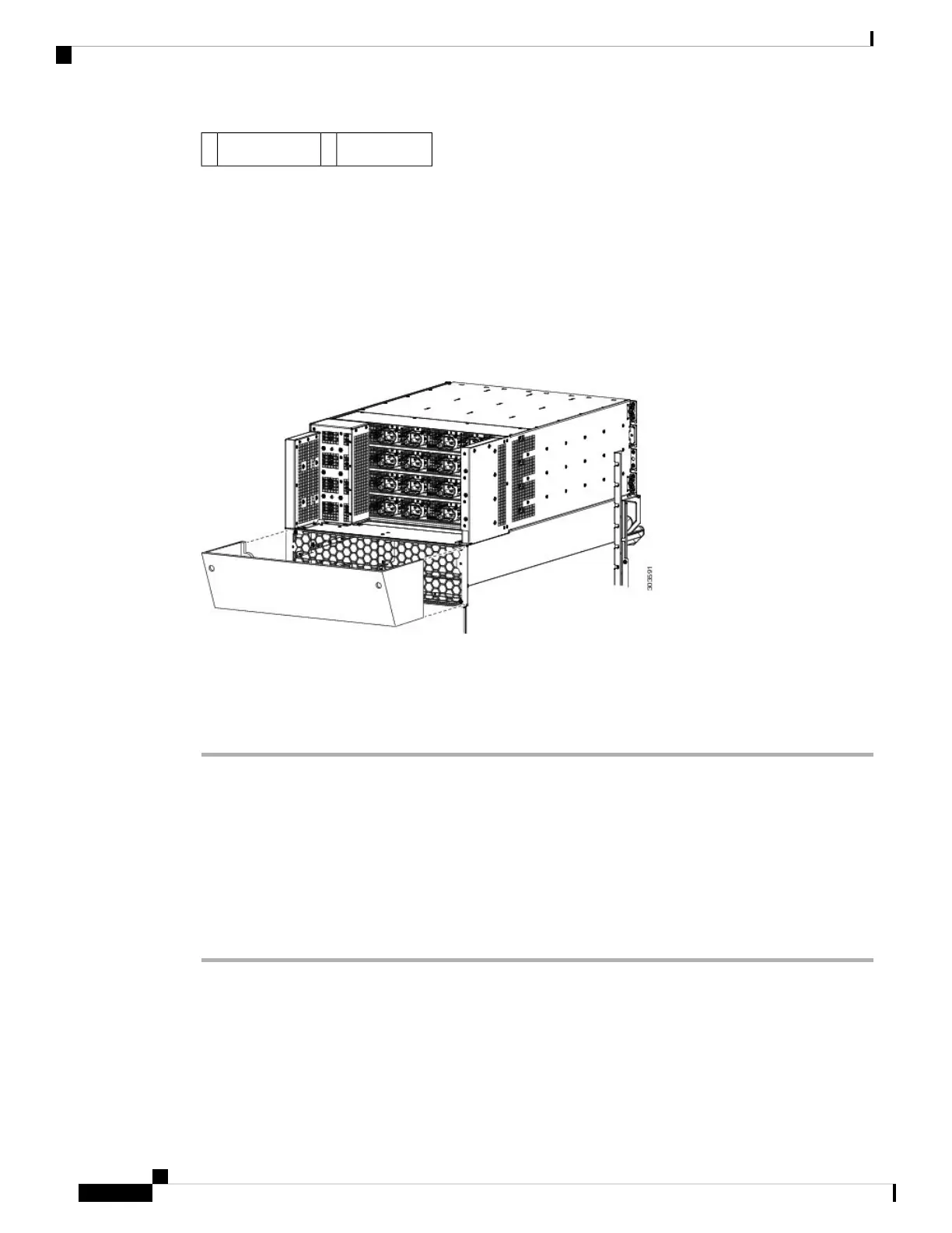
Figure 164: Optional Rear Exhaust Air Deflector on the Cisco ASR 9922 Router
After the chassis has been installed in the rack and all chassis accessories have been attached, you can install
the fan trays, power supply modules, RP cards, FCs and LCs. See Installing Cards and Modules in the Chassis
in the book Cisco ASR 9000 Series Aggregation Services Router Hardware Installation Guide for detailed
installation instructions.
Installing Base Chassis Accessories on the Cisco ASR 9912 Router
The base chassis accessories for the Cisco ASR 9912 Router include (see the figure below):
• One honeycomb cosmetic cover
• One vented bezel to cover the front of the power system
Procedure
Step 1 Attach the honeycomb cosmetic cover to the front of the chassis above the cable management bracket by
aligning the cover above the screw tabs on the chassis.
Step 2 Attach the vented bezel cover by snapping it into place in front of the power system.
You will need to remove the vented bezel cover in order to install the power system. After the power
system is installed, you can re-install the vented bezel cover.
Note
Cisco ASR 9000 Series Aggregation Services Router Hardware Installation Guide
154
Unpacking and Installing the Chassis
Installing Base Chassis Accessories on the Cisco ASR 9912 Router

 Loading...


