Ground pad, where the ground strap screw holes are located.1
Powering the Access Point
The AP supports these power sources:
• DC power – 24–56 VDC
• Power-over-Ethernet (PoE)
The AP can be powered via the PoE input from an inline power injector or a suitably powered switch port.
Depending on the configuration and regulatory domain, the required power for full operation is 802.3bt or
UPOE.
The supporting outdoor power injectors are AIR-PWRINJ-60RGD1 and AIR-PWRINJ-60RGD2 rated at 60W
each. These power injectors support 10/100/1000BASE-T operation only. They do not support the 2.5GBAST-T
(mGig) Ethernet speed.
Note
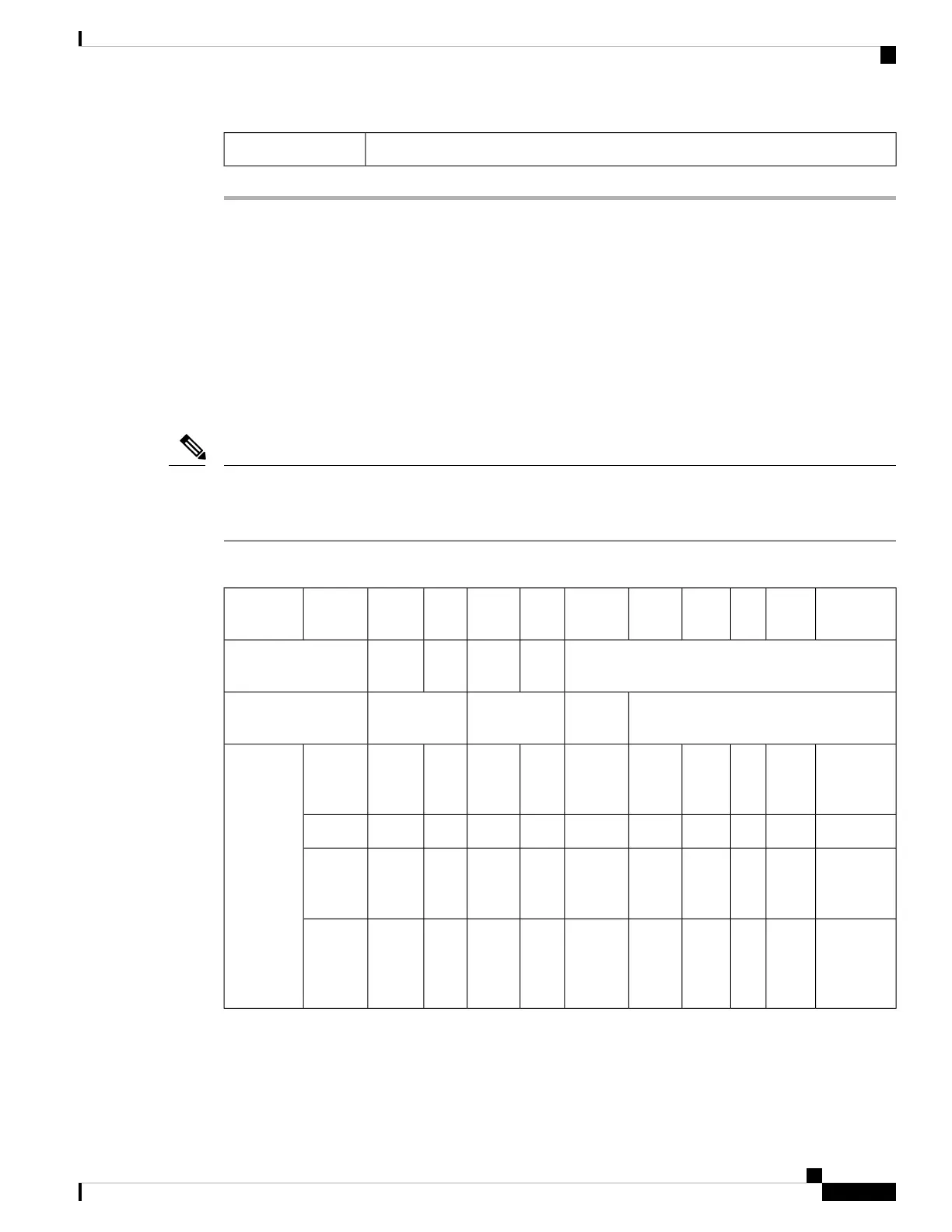
Table 12: Cisco Catalyst 9124AX AP Reduced Power Feature Matrix
NotesPoE-outGbE
PHY
SFP
Module
Ethernet
mGig
AUX
Radio
dBmRadio
1
dBmRadio 0PoE-in/DC
Input
SKU
Per
Path
SSPer
Path
SS
Chillwave5-GHz
Primary radio
2.4-GHz radio
Serving
radios
disabled
NNN1Genabled–
disabled–disabled.3afC9124AXI,
C9124AXD.
C9124AXE
Dual Radio
mode
-NYN1Genabled232x2232x2.3at
PoE output
is 802.3af
compliant
15.4WYY2.5Genabled244x4244x4.3bt /
UPOE
using DC
power
source
≥60W
15.4WYY2.5Genabled244x4244x4DC
input
Cisco Catalyst 9124AX Series Outdoor Access Point Hardware Installation Guide
67
Installation Overview
Powering the Access Point

 Loading...