Step 3
Drill two holes in the wall and insert mounting screws into the holes.
Step 4
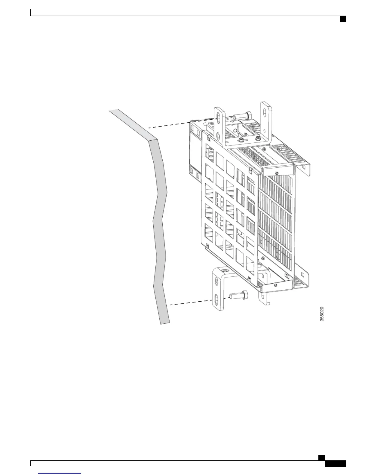
Position the assembly vertically as shown in the figure. Insert screws through the 3/8" or 1/4" hole of mounting
bracket into the wall and secure the assembly against the wall.
Figure 42: Attaching flexible mount assembly to the wall
Step 5
Connect to a power source.
•
To connect the assembly which uses flexible mount with direct-wired junction box
(CDB-MNT-FLEX-DIR) to a power source, use an armored cable. See Electrical Installation section.
CDB-MNT-FLEX-DIR accepts 100V – 277V AC Input.
•
To connect the assembly which uses flexible mount with IEC C14 power junction box
(CDB-MNT-FLEX-C14) to a power source, use country-specific power cord.
CDB-MNT-FLEX-C14 accepts 100V – 240V AC Input.
Step 6
Slide the switch into the flexible mount in a front mounting position as shown in the figure and tighten thumb
screws to secure the switch to flexible mount.
Catalyst Digital Building Series Switch Hardware Installation Guide
61
Switch Installation
Flexible Mounting
 Loading...