35
Installing and Connecting the Router
Power-Supply Modules
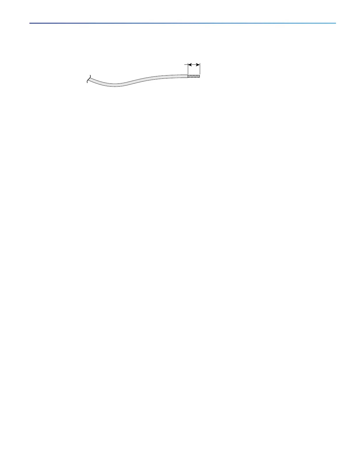
Figure 10 Stripping the Input Power Source Wire
Note: Do not strip more than 0.27 inch (6.8 mm) of insulation from the wire. Stripping more than the recommended
amount of wire can leave exposed wire from the connector after installation.
5. To connect DC power:
Warning: When installing or replacing the unit, the ground connection must always be made first and
disconnected last. Statement 1046
a. Connect the Ground wire (the green or green/yellow lead of the cable) into the terminal marked with the ground
symbol. See item 7 in Figure 9 on page 34.
b. Connect the Positive wire into the terminal screw labeled +.
c. Connect the Negative wire into the terminal screw labeled -.
Note: Ensure that you cannot see any wire lead. Only wire with insulation should extend from the terminal screw.
Note: If you have a low-voltage DC power-supply module, connect the wires to the terminals labeled Lo. See items
5 and 6 in Figure 9 on page 34.
If you have a high-voltage DC power-supply module, connect the wires to the terminals labeled Hi. See items 3
and 4 in Figure 9 on page 34.
Caution: Do not use a power cable to connect the chassis low-voltage DC input to a voltage source. If you
inadvertently plug a cable into a 120 VAC source, the low-voltage supply will be damaged and hazard could
result.
If you need a cable to connect to the low-voltage DC power supply, cut off the plug from the power cord and
hard-wire the Cisco CGR 2010 low-voltage DC input directly to its power source, observing the correct polarity
markings.
d. Use a tie wrap to secure the cable to the central strain relief tab next to the terminal block on the chassis. Secure
the cable immediately adjacent to the terminal block to minimize strain on the cable.
The strain relief mechanism consists of three metal loops built into the chassis next to the terminal block. See
Figure 11 on page 36.
Note: Do not overtighten the tie wrap to the loops, which could damage the wiring insulation. An overtightened tie
wrap could cause cold-flow of the wire insulation, which in turn could cause shorting of the power source to the
chassis.
0.25 in. (6.3 mm)
±
0.02 in. (0.5 mm)
60531

 Loading...

