29
Installing and Connecting the Router
Installing the Router in a Rack
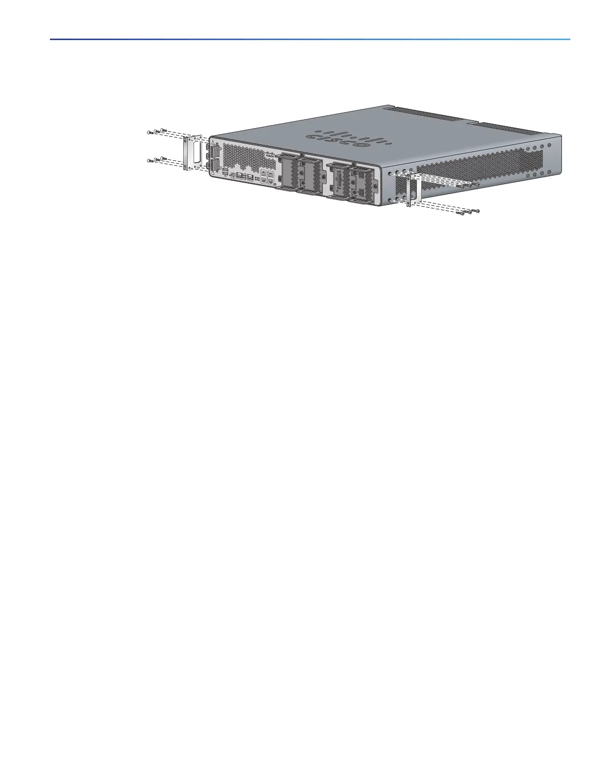
Figure 3 Bracket Installation for Cable-Side Mounting
Caution: Do not over-torque the screws. The recommended torque is 15 to 18 inch-lb (1.7 to 2.0 N-m).
Attach the second bracket to the opposite side of the chassis. Use a number 2 Phillips screwdriver to install the number-8
bracket screws.
Caution: Your chassis installation must allow unrestricted airflow for chassis cooling.
Mounting the Router in a Rack
After you attach the rack-mount brackets to the router chassis, use the screws provided with the rack to install the
chassis in the rack. See Figure 4 on page 30
Note: The screw slots in the brackets are spaced to line up with every second pair of screw holes in the rack. When the
correct screw holes are used, the small threaded holes in the brackets line up with unused screw holes in the rack. If the
small holes do not line up with the rack holes, you must raise or lower the brackets to the next rack hole.
Caution: A space of 1 RU above each Cisco CGR 2010 router is required for sufficient air ventilation.
Figure 4 on page 30 shows a typical installation in a rack.
SFP 0/0
SFP 0/1
GE 0/0
GE 0/1
CONSOLE
AUX
EN
EN
Cisco CGR 2010
PSU2PSU1
L
N
N
L
+
Lo
-
-
Lo
+
277447
-
HI
+
+
HI
-
0
1
EN
SPD
CF
1
PS
2
ACT
SYS
0
1
SL
SL
SLOT 3 SLOT 2
SLOT 1 SLOT 0
CONN CONN
0-3
4-7
CD/LP AL CD/LP AL
P1 P0

 Loading...

