38
Installing and Connecting the Router
Connecting to a Console Terminal or Modem
Note: The maximum current rating for the power disconnect circuit breaker or overcurrent device must be 15 Amps.
Operational power must be internally fused. This fuse cannot be replaced by the user. In the event of the disconnect
device failing, return the unit to the factory for repair.
Replacing Power Supplies and Redundant Power Supplies
Before you perform power supply replacement, read the Safety Warnings, page 77 and disconnect power when noted.
The Cisco CGR 2010 routers have replaceable power supplies. Use a Number 2 Phillips screwdriver to remove or install
the power supply.
Caution: Any combination of power supplies can be inserted into the chassis. Dual power supply configurations are
load sharing in redundancy mode.
A single power supply is sufficient for supporting power needs to the system. A single PSU can be deployed in
either slot 1 (PSU1) or slot 2 (PSU2).
Note: The power supplies are hot swappable. The power supply LED must show it is properly functioning before
removing the other power supply in the router.
Replacing the Cisco CGR 2010 Router Power Supply
For the following steps see Figure 13 on page 38 for the locations of connectors and other components within the Cisco
CGR 2010 router.
To replace the power supply in a Cisco CGR 2010 router:
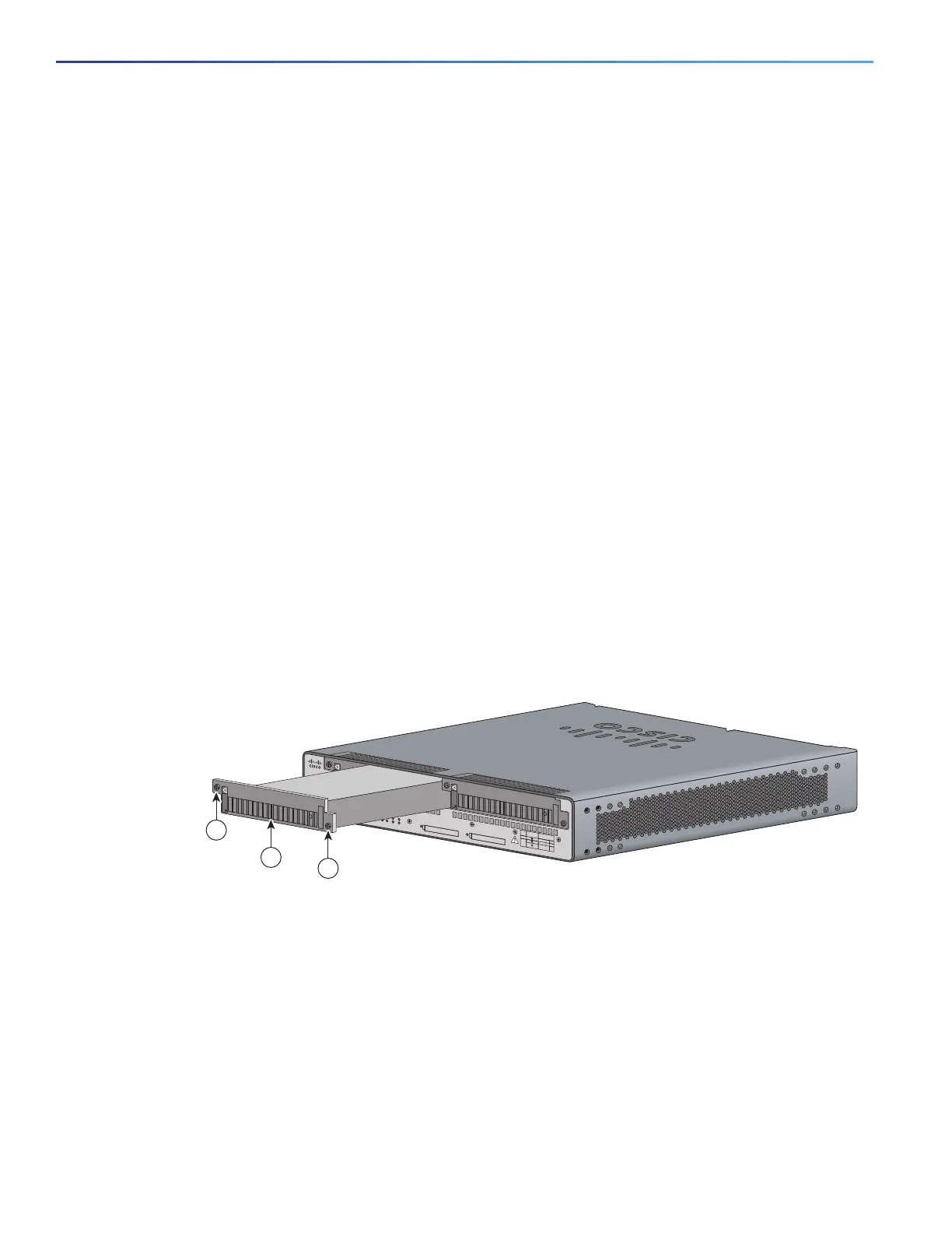
1. Loosen the captive screws that fasten the power supply to the chassis.
2. Pull the power supply out of the chassis. See Figure 13 on page 38.
Figure 13 Removing the Cisco CGR 2010 Router Power Supply
3. Insert the replacement power supply into the chassis. See Figure 13 on page 38.
4. Tighten the captive screws that fasten the power supply to the chassis.
Connecting to a Console Terminal or Modem
The router has asynchronous serial ports and auxiliary ports. These ports provide administrative access to the router
either locally (with a console terminal or a PC) or remotely (with a modem). To configure the router through the Cisco IOS
command-line interface (CLI), you must establish a connection between the router console port and either a terminal or
a PC.
1 Power supply 2 Power supply captive screws
277597
PSU1 PSU2
PSU OK
PWR-150W-HV
SYS SPD SPD SPD SPD 2 0 1
USB
CON
ACT
SFP
0/0
EN
SFP
0/1
EN
GE
0/1
LINK
GE
0/0
LINK
PSU
23 1 CONSOLE
SLOT
CF1
DO NOT REMOVE DURING
NETWORK OPERATION
CF0
DO NOT REMOVE DURING
NETWORK OPERATION
Cisco 2935R
“CAUTION: This unit may have more than one power source.
Disconnect all power sources before servicing to avoid electric chock.”
PS Type
LoV dc
HiV dc
V ac, 50/60 Hz
10A
2A
2A
Input Rating Per Sources
24-60V
100-270V
100-240V ~
PSU1 PSU2
PSU OK
PWR-150W-HV
SYS SPD SPD SPD SPD 2 0 1
USB
CON
ACT
SFP
0/1
EN
SFP
0/0
EN
GE
0/1
LINK
GE
0/0
LINK
PSU
231
CONSOLE
SLOT
CF1 CF0
PSU OK
PWR-150W-HV
DO NOT REMOVE DURING
NETWORK OPERATION
DO NOT REMOVE DURING
NETWORK OPERATION
Cisco Connected Grid Router 2000 Series
CAUTION: This unit may have more than
one power source. Disconnect all power
sources before servicing to avoid
electric shock.
PSU OK
PWR-150W-HV
2
1
2
PS
Type
Input Terminal
Symbol
Input Rating
Per Source
Lo V DC
Hi V DC
Lo 24 - 60 V 10A
100-250V 2A
100-240V
~
2A
50-60 Hz
Hi
or
V AC
~

 Loading...

