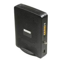
Back Panel Description
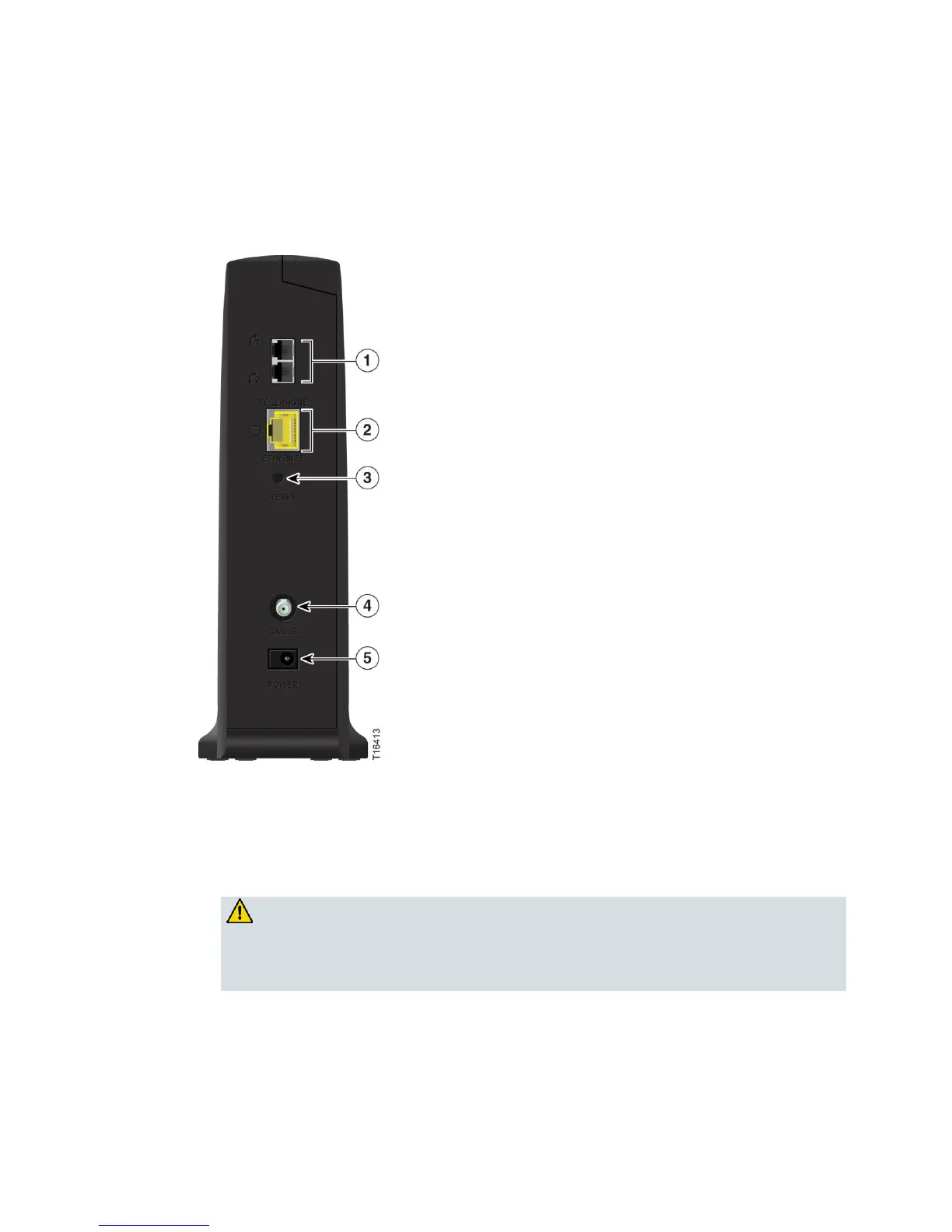
The following illustration identifies the back panel components on the Cisco cable
modem. Descriptions for each component follow the illustration.
1 Telephone 1 and 2—RJ-11 telephone ports connect to home telephone wiring for
conventional telephones.
2 ETHERNET—One RJ-45 Ethernet port is available for connection to the Ethernet
port on your PC or your home network.
3 RESET—Performs software reset of the device.
CAUTION:
The RESET button is for maintenance purposes only. Do not use unless
instructed to do so by your service provider. Doing so may cause you to lose
any settings you have selected.
4 CABLE—F-connector connects to an active cable signal from your service
provider.
5 POWER—Connects the cable modem to the AC power adapter that is provided
with your cable modem.
Important: Use only the power supply provided with your cable modem.
 Loading...