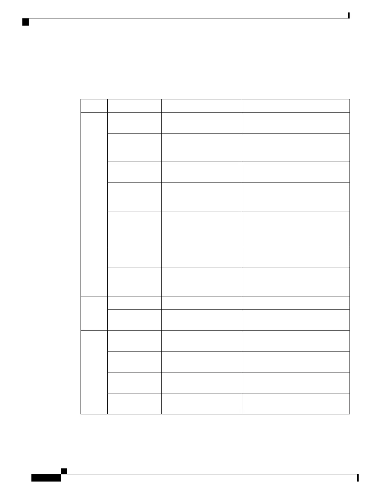
Reference: 2x2 RPD Module LEDs
This section contains LED definition for the 2x2 RPD module. It provides a coarse-grained indication of
device connectivity to field technicians during their installation or repair of the RPD.
NotesState IndicatedLED Pattern or ColorLED
Required - Indicates power goodPower-on - InitializingGreen - 2 Hz Flash
Pattern
System
LEDs
Required - Indicates remote SSHv2 session
possible
IP acquired via DHCP,
synchronizing and acquiring
configuration
Green - 4 Hz Flash
Pattern
No faults detectedSystem status good -
Connections good
Green - Steady
Loose connection, connector faults, water
ingress at connector, wavelength mismatch,
etc.
Connection fault - No physical
connection to CIN or RF
interfaces
Red - 2 Hz Flash
Pattern
Wrong DHCP configuration, unreachable
hosts, failed authentication with CCAP
Core, etc.
Configuration fault - Failed
synchronization or failed to
receive configuration from
Principal CCAP Core
Red - 4 Hz Flash
Pattern
Indicates hardware fault, always indicated
by a steadily illuminated LED.
System fault - Device cannot
initialize
Red - Steady
Vendor-defined LED behavior. May
indicate high error rates in CIN or RF
ports, marginal operating conditions, etc.
Warning - RPD operational but
operation is imperfect
Amber - Various
Indicates connection state
Per [IEEE 802.3x]Flash PatternCIN
LEDs
Indicates possible port failure or a port
which has been configured to be disabled
Ethernet port failure or port
administratively disabled
Unilluminated
At least one pilot and/or alignment tone
active
Power-on - Downstream RF
initializing
2 Hz Flash PatternD-RF
LEDs
Awaiting downstream channel set
configuration
Channel or channels activated4 Hz Flash Pattern
Downstream channels operationalDownstream channel set
configuration obtained
Steadily Illuminated
Fault detected in RF port or RF port muted
by CCAP Core
RF port fault or RF port muteUnilluminated
Troubleshooting
10
Troubleshooting
Reference: 2x2 RPD Module LEDs
 Loading...


