14
Switch Installation
Connecting to Power
Warning: This equipment must be grounded. Never defeat the ground conductor or operate the equipment in the
absence of a suitably installed ground conductor. Contact the appropriate electrical inspection authority or an
electrician if you are uncertain that suitable grounding is available. Statement 1024
Warning: This equipment is intended to be grounded to comply with emission and immunity requirements. Ensure
that the switch functional ground lug is connected to earth ground during normal use. Statement 1064
Caution: To make sure that the equipment is reliably connected to earth ground, follow the grounding procedure
instructions, and use a UL-listed ring terminal lug suitable for number 10-to-12 AWG wire, such as Hollingsworth
part number R3456B or equivalent)
Caution: Use at least a 4 mm2 (0.006 in2) conductor to connect to the external grounding screw.
The ground lug is not supplied with the switch. You can use one of the these options:
Single ring terminal
Two single ring terminals
To ground the switch to earth ground by using the ground screw, follow these steps:
1. Use a standard Phillips screwdriver or a ratcheting torque screwdriver with a Phillips head to remove the ground
screw from the front panel of the switch. Store the ground screw for later use.
2. Use the manufacturer’s guidelines to determine the wire length to be stripped.
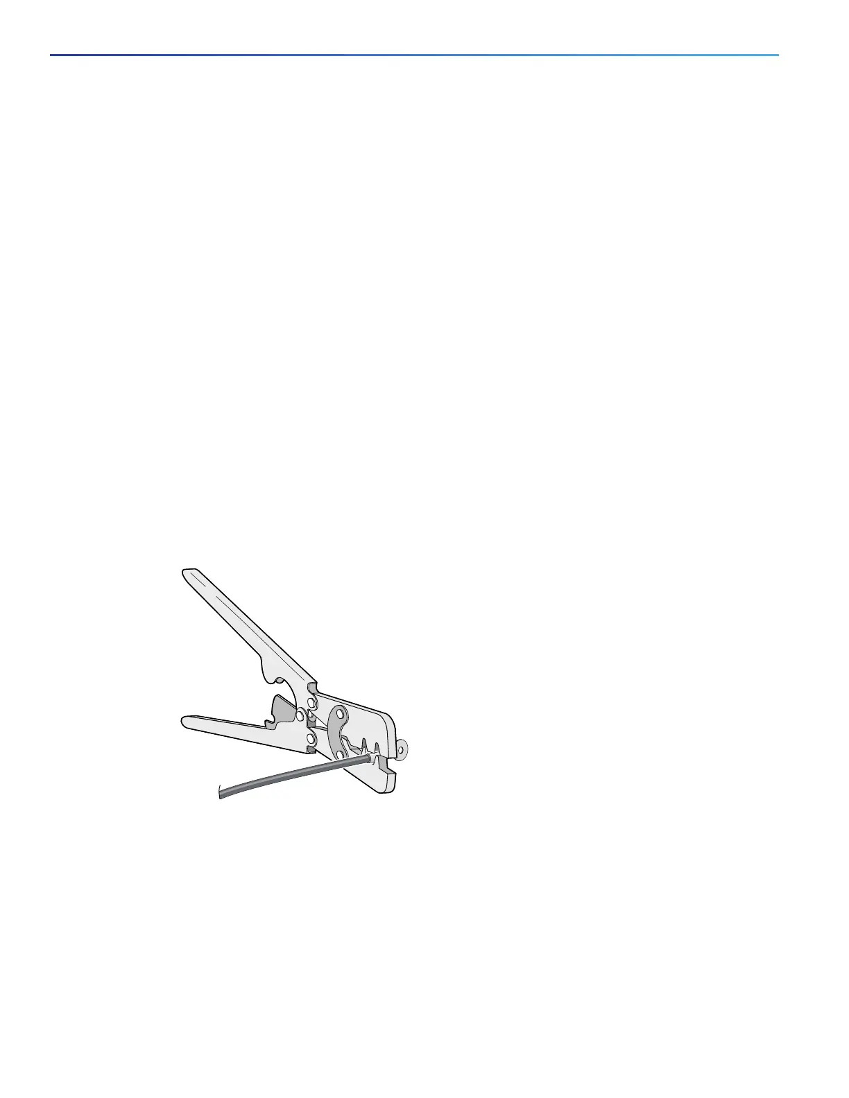
3. Insert the ground wire into the ring terminal lug, and using a crimping tool, crimp the terminal to the wire. See
Figure 5 on page 14. If two ring terminals are being used, repeat this action for a second ring terminal.
Figure 5 Crimping the Ring Terminal
4. Slide the ground screw through the terminal.
5. Insert the ground screw into the functional ground screw opening on the front panel.
6. Use a ratcheting torque screwdriver to tighten the ground screws and ring terminal to the switch top panel. The
torque should not exceed 4.5 in-lb (0.51 N-m). See Figure 6 on page 15.
 Loading...