9-32
Cisco SCE8000 10GBE Installation and Configuration Guide
OL-26784-02
Chapter 9 Removal and Replacement Procedures
Installing a SPA in a SIP
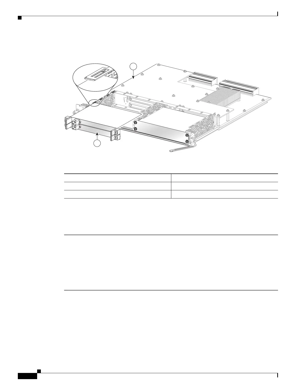
Figure 9-17 illustrates how to install and remove a SPA in the Cisco SCE 8000-SIP.
Figure 9-17 SPA Installation and Removal
Installing a SPA in a SIP
To install a SPA in a SIP, see Figure 9-17 and do the following:
Step 1 At the SCE# prompt, enter reload shutdown and press Enter to power down the Cisco SCE 8000
platform before installing or removing any module.
Step 2 To insert the SPA in the SIP, locate the guide rails inside the SIP that hold the SPA in place. They are at
the top left and top right of the SPA slot and are recessed about an inch, as shown in Figure 9-17.
Step 3 Carefully slide the SPA into the SIP until the SPA is firmly seated in the SPA interface connector. When
fully seated, the SPA might be slightly behind the SIP faceplate.
Step 4 After the SPA is properly seated, fasten the SPA in place with the captive installation screws.
Table 9-1 Componet Indications
This number Indicates this component
1 Cisco SCE 8000-SIP
2 1X10 GBE SPA module
270988
S
TATU
S
2
0
SPA
INTERFACE
PROCESSOR
7600-SIP-400
S
P
A-1X
1
0G
E
-
L
-
V
2
S
P
A-1X
1
0G
E
-
L-V
2
S
TA
T
U
S
ST
A
T
US
1
2

 Loading...


