12
Chapter 3: Connecting the Switch
Stacking Multiple Switches
Linksys One Ready Communications Solution
Chapter
3
If you will use the console interface to configure the Ethernet switch, proceed to ”Console
Configuration” section on page 33 for directions.
If you use the Web-based Utility to configure the Ethernet switch, proceed to ”Web Utility
Configuration” section on page 50.
Stacking Multiple Switches
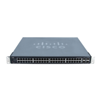
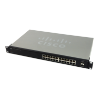
The Stacking configuration provides multiple switch management through a single point as if
all stack master and stack members were a single Ethernet switch. All stack masters are
accessed through a single IP address through which the stack is managed. The stack can be
managed from the web-based interface or the console interface.
You can build stacks by building a new stack from a group of switches, or adding new units
to an existing stack. Stacks can be automatically or manually configured.
Switch software is downloaded separately for each stack member. However, all units in the
stack must be running the same software version.
A stack unit can operate in one of the following modes:
• Stand-alone — A switch operating in standalone mode runs as an independent,
single unit. All ports of a standalone switch operate as normal Ethernet links. A
standalone switch does not participate in a stack even if physically connected to a
stack.
• Stack — Indicates the device operates as a Stacked unit after the system is reset. A
switch operating in stack mode is not an independent unit, but a member of an
organized group of switches known as a stack. A stack consists of one Stack Master
control switch, one Master Backup switch and up to six Stack Member switches. In
some cases, a unit that is not connected to any other units may operate as a “stack–
of-one.”
The Stack Master unit manages the stack and is responsible for the configuration. The Master
Backup Runs as a slave unit and monitors the operation of the stack master. A stack member
NOTE: Two ports of each unit in a stack mode (ports 12
and 24 on GE units, and ports G1 and G2 on FE units)
are reserved for stacking links, and cannot be used for
regular network connections.
Stacking Highlights
• In stacking mode, each Ethernet switch is
given a unique ID, from 1 to 8.
• Stack IDs 1 and 2 are Master-Enabled units.
• All Ethernet switches in the stack must run the
same version of software.
• The Stack Master switch maintains the
configuration.
• Stack cannot combine Linksys SFE2000 and
SGE2000 family Ethernet switches.
• By factory default, Ethernet switches boot in
stacking mode.
• Stack ID can be user assigned or
automatically assigned.
• Stacking ports are available to user in
standalone mode as regular network ports.
• Settings are applied only to the master unit;
certain changes take place only after reset.
 Loading...


