3-12
Cisco UCS C220 M4 Server Installation and Service Guide
OL-32473-01
Chapter 3 Maintaining the Server
Installing or Replacing Server Components
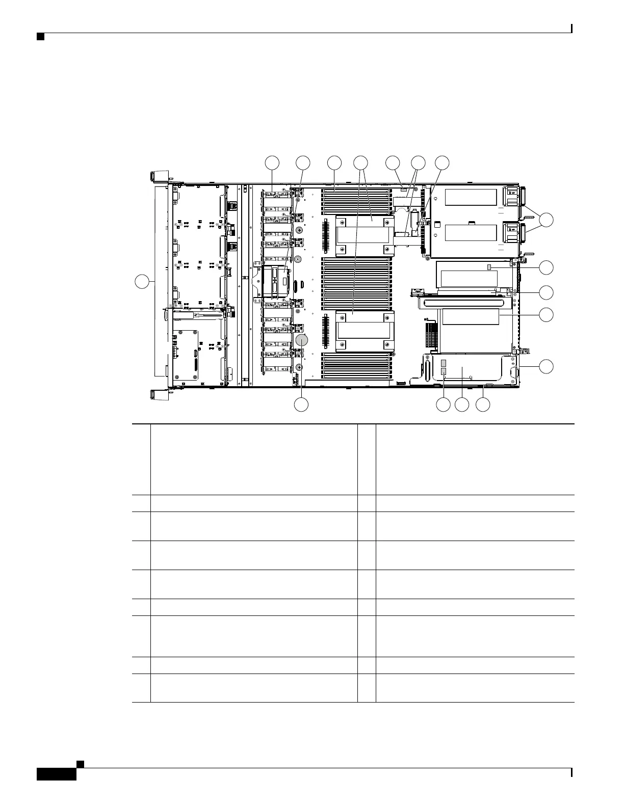
Replaceable Component Locations
This section shows the locations of the field-replaceable components. The view in Figure 3-5 is from the
top down with the top cover and air baffle removed.
Figure 3-5 Replaceable Component Locations
The Technical Specifications Sheets for all versions of this server, which include supported component
part numbers, are at Cisco UCS Servers Technical Specifications Sheets.
1 Drive bays 1–8 support SAS/SATA drives.
SFF, 8-drive version only: Drive bays 1 and 2
support SAS/SATA and NVMe PCIe SSDs.
NVMe SSDs require PCIe riser version 2B in
the server to provide the PCIe bus connection.
10 Trusted platform module (TPM) socket on
motherboard (not visible in this view)
2 Cooling fan modules (six) 11 PCIe riser 2 (half-height PCIe slot 2)
3 Supercap Power Module (RAID backup)
mounting bracket
12 PCIe riser 1 (full-height PCIe slot 1)
4 DIMM sockets on motherboard (24) 13 Modular LOM (mLOM) connector on chassis
floor
5 CPUs and heatsinks (up to two) 14 Cisco modular RAID controller PCIe riser
(dedicated riser with horizontal socket)
6 Embedded SATA RAID header for RAID 5 key 15 Cisco modular RAID controller card
7 SD card bays on motherboard (two) 16 Embedded SATA RAID mini-SAS
connectors on motherboard (not visible in
this view)
8 Internal USB 3.0 port on motherboard 17 RTC battery on motherboard
9 Power supplies (up to two, hot-swappable
when redundant as 1+1)
352978
FAN 6
FAN 5
FAN 4
FAN 3
FAN 2
FAN 1
CPU 2
CPU 1
PSU 2
PSU 1
PCIe Riser 1
PCIe Riser 2
SD 1
SD 2
1
2
4 5
67
8
9
10
11
12
13
1617 15 14
3
 Loading...


