3-5
Cisco UCS C220 M4 Server Installation and Service Guide
OL-32473-01
Chapter 3 Maintaining the Server
Status LEDs and Buttons
Rear Panel LEDs and Buttons
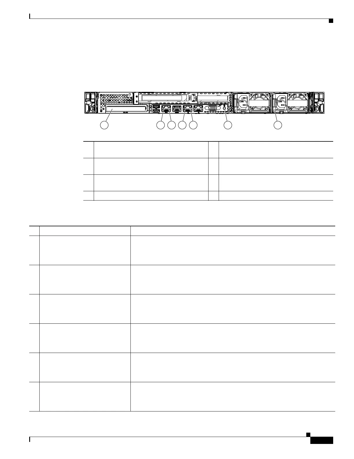
Figure 3-2 shows the rear panel LEDs and buttons. Table 3-2 defines the LED states.
Figure 3-2 Rear Panel LEDs and Buttons
1 Optional mLOM card LEDs
(not shown, see Table 3-2)
5 1-Gb Ethernet link status LED
2 1-Gb Ethernet dedicated management link
status LED
6 Rear unit identification button/LED
3 1-Gb Ethernet dedicated management link
speed LED
7 Power supply status LED
4 1-Gb Ethernet link speed LED
Table 3-2 Rear Panel LEDs, Definitions of States
LED Name State
1 Optional mLOM 10-Gb SFP+
(there is a single status LED)
• Off—No link is present.
• Green, steady—Link is active.
• Green, blinking—Traffic is present on the active link.
1 Optional mLOM 10-Gb BASE-T
link speed
• Off—Link speed is 10 Mbps.
• Amber—Link speed is 100 Mbps/1 Gbps.
• Green—Link speed is 10 Gbps.
1 Optional mLOM 10-Gb BASE-T
link status
• Off—No link is present.
• Green—Link is active.
• Green, blinking—Traffic is present on the active link.
2 1-Gb Ethernet dedicated
management link speed
• Off—Link speed is 10 Mbps.
• Amber—Link speed is 100 Mbps.
• Green—Link speed is 1 Gbps.
3 1-Gb Ethernet dedicated
management link status
• Off—No link is present.
• Green—Link is active.
• Green, blinking—Traffic is present on the active link.
4 1-Gb Ethernet link speed
• Off—Link speed is 10 Mbps.
• Amber—Link speed is 100 Mbps.
• Green—Link speed is 1 Gbps.
353089
mLOM
PCIe 01 PCIe 02
PSU 01 PSU 02
1 32 5 6 74
12
 Loading...


