3-65
Cisco UCS C220 M4 Server Installation and Service Guide
OL-32473-01
Chapter 3 Maintaining the Server
Installing or Replacing Server Components
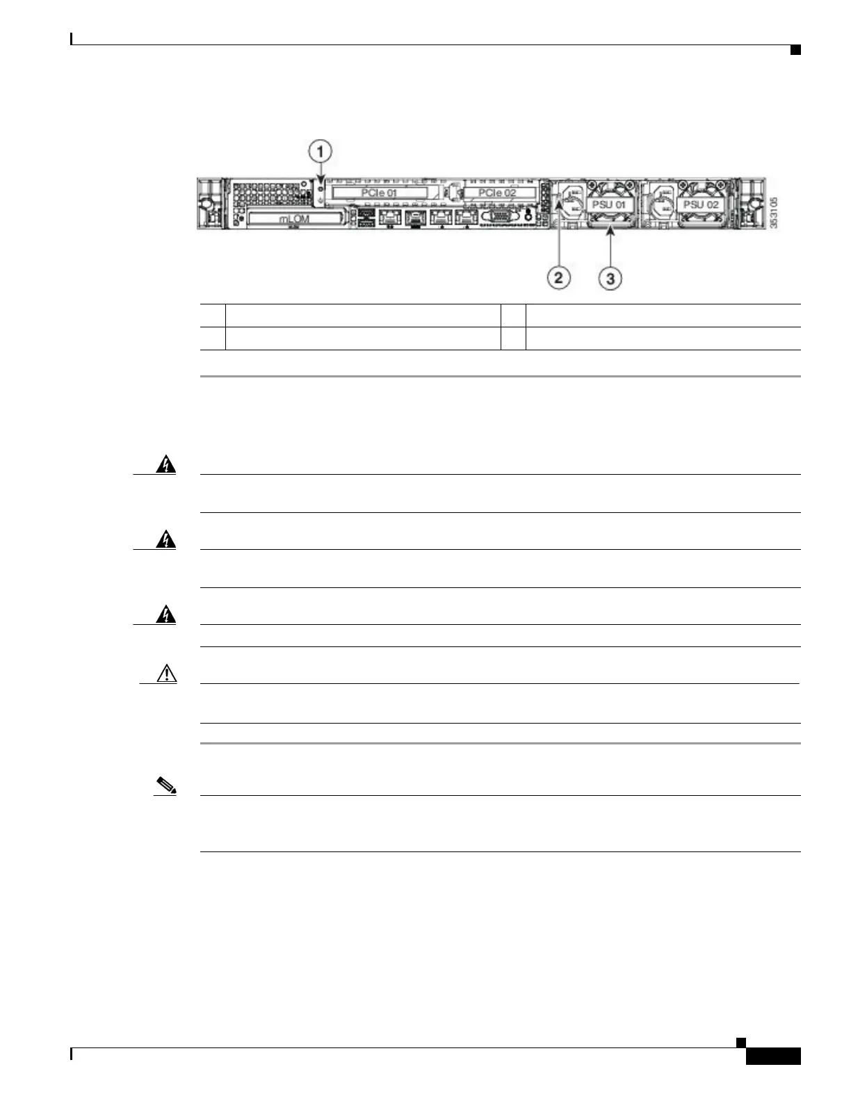
Figure 3-32 Removing and Replacing Power Supplies
Installing a DC Power Supply (UCSC-PSUV2-1050DC)
Warning
A readily accessible two-poled disconnect device must be incorporated in the fixed wiring.
Statement 1022
Warning
This product requires short-circuit (overcurrent) protection, to be provided as part of the building
installation. Install only in accordance with national and local wiring regulations. Statement 1045
Warning
Installation of the equipment must comply with local and national electrical codes. Statement 1074
Caution Before beginning this wiring procedure, turn off the DC power source from your facility’s circuit breaker
to avoid electric shock hazard.
Step 1 Turn off the DC power source from your facility’s circuit breaker to avoid electric shock hazard.
Note The required DC input cable is Cisco part CAB-48DC-40A-8AWG. This 3-meter cable has a 3-pin
connector on one end that is keyed to the DC input socket on the power supply, as shown in Figure 3-33.
The other end of the cable has no connector so that you can wire it to your facility’s DC power.
Step 2 Wire the non-terminated end of the cable to your facility’s DC power input source.
Step 3 Connect the terminated end of the cable to the socket on the power supply. The connector is keyed so
that the wires align for correct polarity and ground, as shown in Figure 3-33.
Step 4 Return DC power from your facility’s circuit breaker.
Step 5 See Installation Grounding, page 3-66 for information about additional chassis grounding.
1 Hole for chassis grounding lug screw 3 Power supply handle
2 Power supply release lever
 Loading...


