Cisco WAP571 Wireless Access Point 2
Cisco WAP571 Wireless-AC/N Premium
Dual Radio Access Point with PoE Setup
Features
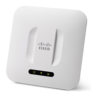
Front Panel
The front panel of the device consists of a single system LED. For a full
description of the colors of the light and its indications, see Verifying the
Hardware Installation, page 6.
A Kensington lock slot is found above the light.
Back Panel
The back panel of the device has two RJ-45 Ethernet ports. Facing the
back of the device, the right port (labeled “ETH0/PD”) is an 802.3at &
802.3af Power over Ethernet (PoE) port which is used to power your
device. The left port (labeled “ETH1”) is a general Gigabit Ethernet LAN
interface. Both are auto-sensing, Gigabit Ethernet (802.3) ports used to
connect your WAP devices to network devices, such as computers,
routers, or switches. We strongly recommend that you use a Category
5e or better cable for Gigabit connectivity.
The side panel of the device has a Reset button. See Rebooting the
Devices or Returning them to their Factory Default Settings, page 10
for information on the Reset button.
Default Setting
If you are using a Cisco RV Series router, the default range for the DHCP
assigned address is from 192.168.1.100 to 192.168.1.254. Any device
connecting to the same LAN will be assigned an IP address in this range.
If your network does not have an existing DHCP server, the WAP571 will
start a DHCP server for WLAN stations and stop the DHCP client when
WAP571 is in factory default. The DHCP server will assign the IP address
from 192.168.1.20 to 192.168.1.100.
Parameter Default Value
Username cisco
Password cisco
LAN IP Address DHCP address assigned
by server
Fallback LAN IP 192.168.1.245
Subnetwork Mask 255.255.255.0
 Loading...