—30—
1. Turn off the power.
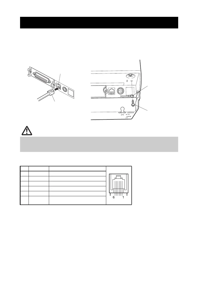
2. Confirm the orientation of the cash drawer kick-out cable connector and connect it
to the cash drawer kick-out connector at the back of the printer.
3. Remove the screw for the ground wire.
4. Screw the cash drawer’s ground wire to the body of the printer.
(1) Connector pin configuration
(2) Electric characteristics
1) Drive voltage: 24 VDC
2) Drive current: Approx. 1 A max. (not to exceed 510 ms.)
3) DRSW signal: Signal levels: “L” = 0 to 0.8 V, “H” = 2 to 3.3 V
(3) DRSW signal
DRSW signal status can be tested with the DLE+EOT, GS+a, or GS+r
command or at pin 34 on the parallel interface port.
3.6 Connecting the Cash Drawer
Connect only the cash drawer kick-out cable connector to the cash drawer kick-out
connector. (Do not connect a telephone line.)
Signals cannot be output from the cash drawer kick-out connector while printing.
No. Signal Function
1 FG Frame ground Connector used:
TM5RJ3-66 (Hirose) or
equivalent
Applicable connector:
TM3P-66P (Hirose) or
equivalent
2 DRAWER1 Cash drawer 1 drive signal
3 DRSW Cash drawer switch input
4 VDR Cash drawer drive power supply
5 DRAWER2 Cash drawer 2 drive signal
6 GND Signal ground (common ground on
circuits)
Cash drawer kick-out
connector
Cash drawer kick-out cable
connector
Ground wire
Screw for ground
wire
 Loading...