36
Electrical connections
– The control line between the outdoor unit and
the indoor unit is BUS type. The addresses are
configured on site during installation.
w
a
CAUTION
Earth only at one point in the system since
multiple points can generate transmission
noise.
m
CAUTION
Within a group, connect only indoor units of
the same type (wall, ducted, recessed).
Connect the various indoor and outdoor units as shown
in the diagram below.
Fig. 55
1
Bus between outdoor unit and indoor units
Close the chain between P and Q in the last indoor unit
with the 120Ω resistor supplied with the outdoor unit.
Do not return the bus to the outdoor unit.
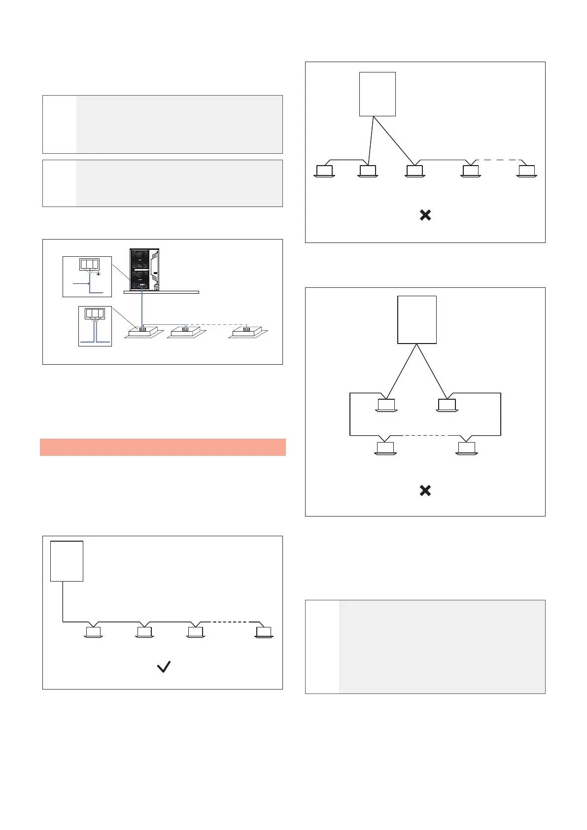
5.4 Wiring method
Communication with indoor unit: The communication line
P, Q, E must be connected in a chain leading from the
outdoor unit to each indoor unit and up to the last indoor
unit, connecting a 120Ω heater between terminals P and
Q. The correct and incorrect methods of connection are
shown below:
1
P Q E
P Q E P Q E P Q E P Q E
2 2 2 2
Fig. 56
1
Outdoor unit
2
Indoor unit
1
P Q E P Q E P Q E
P Q E
P Q E
2 2 2 2 2
Fig. 57
1
Outdoor unit
2
Indoor unit
Do not connect two chains from a single outdoor unit.
1
P Q E
P Q E
P Q E
P Q E
P Q E
2 2
22
Fig. 58
1
Outdoor unit
2
Indoor unit
After the last indoor unit, the communication cables must
not be led back to the outdoor unit as to do so would
form a closed circuit.
l
WARNING
The cross-section of each core of the
communication cabling must not be less than
0.75 mm
2
and the length must not exceed
1200 m. A communication error can occur
when the communication cabling exceeds
these limitations.
N1
1
N
2 N10
P Q E
P Q E
P Q E
P Q E P Q E P Q E
 Loading...