19
Refrigerant piping
4 REFRIGERANT PIPING
4.1 Installation of the refrigerant piping
Below are the guidelines for compliant installation of the
refrigerant piping
Put the outdoor unit in place
Put the indoor unit in place
Put the pipes in place
Blow with nitrogen
Perform welding
Make the connection to the units
Perform the tightness test
Carry out pressing and pressurisation
To perform all the operations correctly, you need the
following equipment:
– Pipe cutter
– Flaring tool
– Tube bending machine
– Vacuum pump
– Digital vacuum gauge
– Manifold and fittings
– Cylinder of nitrogen
– Electronic leak detector with sensitivity according
to current regulations.
l
WARNING
Pay attention to the maximum measurements
of the refrigerant piping. See paragraph “2.5
Length of refrigerant piping” page 13 .
l
WARNING
Use deoxidised phosphorous copper piping
for the refrigerant (seamless copper alloy
piping and tubing) compliant with local
regulations.
l
WARNING
Use piping suitable for use with R410A.
l
WARNING
Be careful not to touch the components when
connecting the pipes.
Keep the ends of the pipes sealed until installation to
prevent the ingress of polluting agents such as dust,
water and dirt.
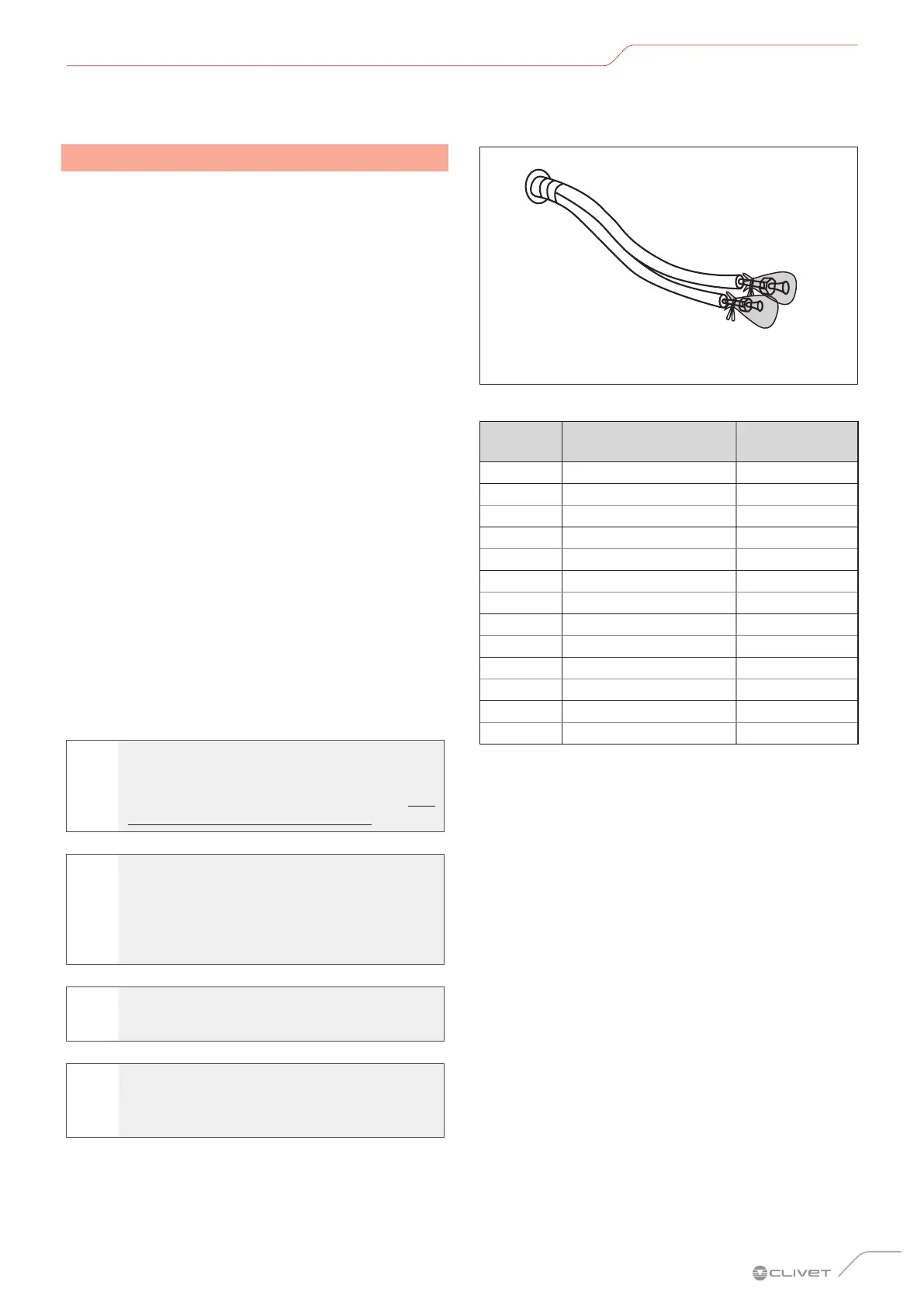
Fig. 22
For the diameter to be used refer to the following table
Ø (mm) Ø (inches)
Radial
thickness (mm)
6.35 1/4” 0.8
9.52 3/8” 0.8
12.7 1/2” 0.8
15.9 5/8” 1.0
19.1 3/4” 1.0
22.2 7/8” 1.2
25.4 1” 1.2
28.6 1” - 1/8” 1.3
31.8 1” - 1/4” 1.5
38.1 1” - 3/8” 1.5
41.3 1” - 5/8” 1.5
44.5 1” - 3/4” 1.5
54.0 2” - 1/8” 1.8
Blow nitrogen through the sections pre-welded in the
workshop to expel any dust.
Pipes should only be cut using roller pipe cutters (do not
use a hacksaw).
Dirt that penetrates the pipes when in use could clog the
expansion valves, the capillaries or enter the compressor,
causing the latter to malfunction.
 Loading...