InteliGen
NT
, InteliSys
NT
, InteliMains
NT
– Troubleshooting Guide,
SW version IGS-NT-3.1.0, IM-NT-3.1.0, ©ComAp – August 2018 19
IGS-NT Troubleshooting Guide.pdf
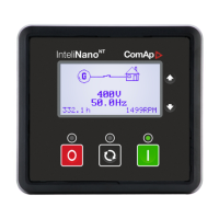
In this case 100 kW is still burned in each load bank phase, but PF in phases L2 and L3 is not
1 from controller point of view. PF in phases L2 and L3 is -0,5 due to phase shift between
voltages and currents which is caused by CTs swapping. The result is that total generator
power displayed by controller is 0 kW. Calculation is as follows:
U
L1
=U
L2
=U
L3
= 400 V
I
L1
=I
L2
=I
L3
= 250 A
PF
L1
=1
PF
L2
=PF
L3
= -0,5
P
L1
= U
L1
xI
L1
xPF
L1
=400x250x1= 100 kW
P
L2
=P
L3
=U
L2
xI
L2
xPF
L2
= -50 kW
P
TOT
=P
L1
+P
L2
+P
L3
= 100+(-50)+(-50)= 0 kW
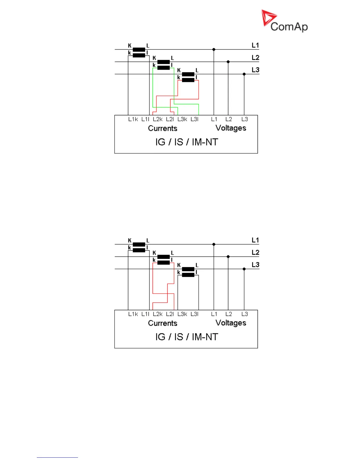
Example of incorrect connection with wrong CT polarity in phase L2:
In this case 100 kW is still burned in each load bank phase, but PF in phase L2 is not 1 from
controller point of view. PF in phase L2 is -1, because current goes in the opposite way due to
wrong CT polarity. The result is that total generator power displayed by controller is 100 kW.
Calculation is as follows:
U
L1
=U
L2
=U
L3
= 400 V
I
L1
=I
L2
=I
L3
= 250 A
PF
L1
=PF
L3
=1
PF
L2
= -1
P
L1
=P
L3
= U
L1
xI
L1
xPF
L1
=400x250x1= 100 kW
P
L2
=U
L2
xI
L2
xPF
L2
= 400x250x(-1)= -100 kW

 Loading...