ALIGNMENT PROCEDURE
IMPORTANT:
IN ORDER TO OBTAIN MAXIMUM CUTTING
ACCURACY, THE FOLLOWING SIX STEPS
MUST BE CAREFULLY FOLLOWED.
BECOME THOROUGHLY FAMILIAR WITH
THESE STEPS SO THAT YOU CAN ALWAYS
MAINTAIN YOUR SAW IN PROPER
ALIGNMENT. THE ACCURACY OF EACH
ADJUSTMENT IS ALWAYS DEPENDENT
UPON THE ACCURACY OF THE PRECEDING
ADJUSTMENT.
Afte_ following the 6 step assembly and alignment
procedure and the Basic Saw operation section refer to
Trouble Shooting section if any difficulty is experienced
when performing any sawing operation.
STEP ONE
NOTE: The following adjustment, performed properly, will
result in the work table being parallel to the arm.
ATTACHING AND LEVELING TABLE MOUNTING
SUPPORT CHANNELS.
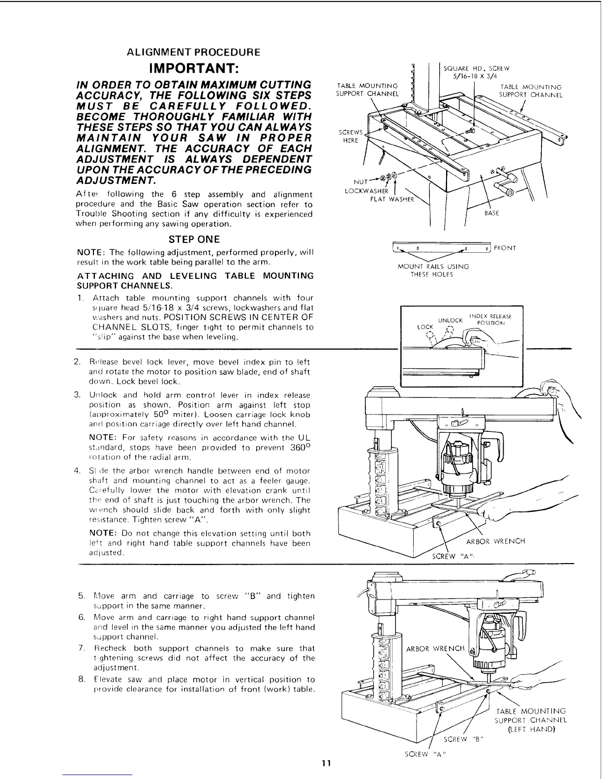
1. Attach table mounting support channels with four
s_tuare head 5/1 6-18 x 3/4 screws, Iockwashers and flat
washers and nuts. POSITION SCREWS IN CENTER OF
CHANNEL SLOTS, finger tight to permit channels to
"stip" against the base when leveling.
2.
3.
4.
Release bevel lock lever, move bevel index pin to left
and rotate the motor to position saw blade, end of shaft
down. Lock bevel lock.
Unlock and hold arm control lever in index release
position as shown. Position arm against left stop
(approximately 50 ° miter). Loosen carriage lock knob
and position carriage directly over left hand channel.
NOTE: For safety reasons in accordance with the UL
standard, stops have been provided to prevent 360 °
rotation of the radial arm.
SI de the arbor wrench handle between end of motor
shaft and mounting channel to act as a feeler gauge.
C_efully lower the motor with elevation crank until
the end of shaft is just touching the arbor wrench. The
wrench should slide back and forth with only slight
resistance. Tighten screw "A".
NOTE: Do not change this elevation setting until both
left and right hand table support channels have been
adjusted.
TABLE MOUNTING
SUPPORT CHANNEL
\
SQUARE HDo SCREW
s/16-18 x 314
TABLE MOUNT! NG
SUPPORTCHANNEL
SCREWS
HERE
LOCKWASHER /
FLAT WASHER
BASE
MOUNT RAILS USING
THESE HOLES
_ FRONT
INDEX RELEASE
UNLOCK POSITION'
LOCK _'_
ARBOR WRENCH
SCREW "A "_
5. Move arm and carriage to screw "'B" and tighten
support in the same manner.
6. Move arm and carriage to right hand support channel
arid level in the same manner you adjusted the left hand
support channel.
7. Recheck both support channels to make sure that
t ghtening screws did not affect the accuracy of the
adjustment.
8. Elevate saw and place motor in vertical position to
t_rovide clearance for installation of front (work) table.
I _ _ //_ TABLE MO_UNTING
I ' _ SUPPORT CHANNEL
SCREW "B"
SCREW "A"
11
 Loading...